

Input current is established before the bus
HCS03.1E-W0350-A-05-NNBV accepts the -05 three-phase supply through X3. Its rectifier and charging-current limitation build the DC bus without exposing the capacitor bank directly to uncontrolled inrush.
Welcome to Moore Automation Limited

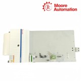
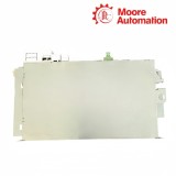
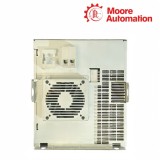

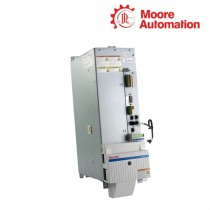
|
Copy and share this link on social network or send it to your friends
Copy| Product Name | Bosch Rexroth HCS03.1E-W0350-A-05-NNBV IndraDrive C Compact Converter |
| Item NO. | 2942582 |
| Weight | 0.1 kg = 0.2205 lb = 3.5274 oz |
| Category | BOSCH |
| Brand | BOSCH |
| Creation Time | 2026-11-19 |
Bosch Rexroth HCS03.1E-W0350-A-05-NNBV is an IndraDrive C HCS03 compact converter in the 400–500 V mains class. Its 350 A maximum-current frame combines input rectification, a high-capacity DC bus, braking control and the motor inverter in the 350 mm-wide HCS03 housing.
The input stage of HCS03.1E-W0350-A-05-NNBV is rated at 201 A and is paired with the 250 A branch-protection row. With the assigned choke the DC bus is rated at 120 kW; the inverter draws from that bus and supplies up to 200 A continuously at 4 kHz through X5.
Forced-air cooling removes 2300 W of continuous loss from HCS03.1E-W0350-A-05-NNBV. The W0350 row is limited to 4 and 8 kHz switching, while X9 uses the high-current external-resistor connection group and L+/L− remain the separate DC-bus terminals.

| Attribute | HCS03.1E-W0350-A-05-NNBV |
|---|---|
| 01Brand | Bosch Rexroth |
| 02Product type | Compact converter |
| 03Series | IndraDrive C HCS03 |
| 04Rated mains input | 3 × AC 400…500 V |
| 05Rated mains current | 201 A |
| 06Branch-circuit fuse | 250 A |
| 07Maximum output current | 350 A |
| 08Continuous output current at 4 kHz | 200 A |
| 09Rated DC-bus power with choke | 120 kW |
| 10Maximum DC-bus power with choke | 210 kW |
| 11Switching frequencies | 4 / 8 kHz |
| 12Continuous power dissipation | 2300 W |
| 13Control-voltage input | 24 V ±20% |
| 14Housing width | 350 mm |
| 15External-resistor cable cross-section | 50 mm² |
The largest HCS03 frame coordinates charging, DC-bus storage, inverter switching and braking around one high-current electrical node.
HCS03.1E-W0350-A-05-NNBV accepts the -05 three-phase supply through X3. Its rectifier and charging-current limitation build the DC bus without exposing the capacitor bank directly to uncontrolled inrush.
In HCS03.1E-W0350-A-05-NNBV, L+/L− sit between the input stage and the motor inverter. The braking transistor monitors this same bus and transfers regenerative energy to the connected resistor circuit when required.
The 200 A continuous output of HCS03.1E-W0350-A-05-NNBV is attached to 4 kHz operation. A frequency change alters switching loss, so the value cannot be detached from its stated condition.
Power conductors, motor auxiliaries, braking cables and cooling air each occupy a defined boundary around the W0350 frame.
The 250 A protective-device row for HCS03.1E-W0350-A-05-NNBV corresponds to its 201 A rated mains input. It protects the input branch and does not describe the motor-output current.
X5 on HCS03.1E-W0350-A-05-NNBV carries motor power; X6 carries temperature and holding-brake circuits. This division prevents auxiliary conductors from being grouped with the three high-current phase outputs.
The forced-air path of HCS03.1E-W0350-A-05-NNBV must remove 2300 W at continuous operation. Mounting clearances and cabinet exhaust capacity therefore form part of the electrical loading boundary.
The motor-temperature and holding-brake circuits use X6, separate from the three motor-power phases at X5. Keep this requirement with HCS03.1E-W0350-A-05-NNBV.
HCS03.1E-W0350-A-05-NNBV should be recorded with this result: the W0350 row is documented for 4 and 8 kHz only, so 12 and 16 kHz must not be copied from smaller HCS03 frames.
HCS03.1E-W0350-A-05-NNBV: Use 200 A at 4 kHz as the documented continuous output condition; W0350 is the maximum-current class, not a continuous-current statement.
For HCS03.1E-W0350-A-05-NNBV, use the 2300 W continuous dissipation figure together with the documented forced-air mounting arrangement.
L+ and L− expose the DC bus between the rectifier/braking section and the motor inverter. This condition belongs to HCS03.1E-W0350-A-05-NNBV.
When checking HCS03.1E-W0350-A-05-NNBV, the 201 A rated mains input is paired with the 250 A fuse row and its corresponding conductor data.

Moore Automation uses one enquiry record to organize model confirmation, quotation details, delivery timing and shipment communication. The company reference material calls for accurate lead-time information and tracking updates instead of leaving the customer to coordinate separate contacts.
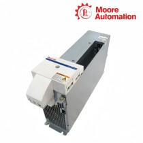
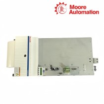
For HCS03.1E-W0350-A-05-NNBV, the type plate and X3, L+/L−, X5, X6 and X9 photographs can be attached to that record before commercial review.
Moore Automation Sales Team
Copyright © 2004–2026 www.mvme.cn. All rights reserved.
Disclaimer: Moore Automation Limited is an independent reseller and is not an authorized distributor or representative of the manufacturers featured on this website. Product names and trademarks belong to their respective owners.
No related record found