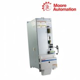
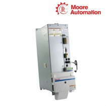
HMS01.1N-W0150-A-07-NNNN and HMS01.1N-W0054-A-07-NNNN are Bosch Rexroth IndraDrive M HMS01 single-axis inverters that convert 254–750 V DC-bus power into separate controlled three-phase motor outputs. The two models perform the same position in the drive chain, but their inverter stages, connection cross-sections and cooling frames belong to widely different current classes.
The W0150 member of HMS01.1N-W0150-A-07-NNNN and HMS01.1N-W0054-A-07-NNNN reaches 150 A maximum and 99.7 A continuous at 4 kHz; the W0054 member reaches 54 A maximum and 35.0 A continuous at the same frequency. Their output-frequency limits follow the selected switching frequency, while standstill current is reduced below the defined 2–4 Hz threshold for thermal protection.
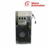
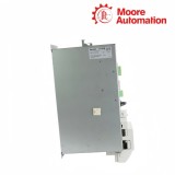
Mechanically, HMS01.1N-W0150-A-07-NNNN and HMS01.1N-W0054-A-07-NNNN share a 440 mm height and 262 mm depth. W0150 uses a 150 mm-wide, 12.74 kg frame with 185 m³/h airflow, while W0054 uses a 75 mm-wide, 6.68 kg frame with 56 m³/h airflow; both retain the same 80 mm top and 100 mm bottom clearance rule.
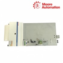
HMS01.1N-W0150 frame dimensions and required clearance around the motor-cable area.
02
Product Data
Attribute
HMS01.1N-W0150-A-07-NNNN
HMS01.1N-W0054-A-07-NNNN
Brand
Bosch Rexroth
Bosch Rexroth
Product type
Single-axis inverter
Single-axis inverter
DC-bus input
254…750 V DC
254…750 V DC
Maximum output current at 4 kHz
150.0 A
54.0 A
Continuous output current at 4 kHz
99.7 A
35.0 A
Continuous output current at 8 kHz
67.5 A
20.0 A
Control-voltage input
24 V ±20%
24 V ±20%
Mass
12.74 kg
6.68 kg
Housing height
440 mm
440 mm
Housing width
150 mm
75 mm
Housing depth
262 mm
262 mm
Forced-air volume
185 m³/h
56 m³/h
Top / bottom clearance
80 / 100 mm
80 / 100 mm
03
Energy flow from the common bus to two motors
Each inverter is a separate branch from the shared DC bus, with its own switching bridge, current measurement and motor terminals.
01
DC input boundary
L+ and L- feed both members of HMS01.1N-W0150-A-07-NNNN and HMS01.1N-W0054-A-07-NNNN from the system DC bus. Each inverter monitors that incoming bus locally before its switching bridge can form a motor output, so a shared upstream source does not merge the two axis branches.
02
W0150 motor branch
The W0150 device in HMS01.1N-W0150-A-07-NNNN and HMS01.1N-W0054-A-07-NNNN directs bus energy through its own switching bridge, current measurement and motor terminals. Its control loop acts on the feedback and command assigned to that motor, independently of the W0054 axis.
03
W0054 motor branch
The W0054 device in HMS01.1N-W0150-A-07-NNNN and HMS01.1N-W0054-A-07-NNNN repeats the same functional chain with a smaller power and cooling envelope. It receives the common bus but retains separate switching, current supervision and motor conductors.
04
Frequency, standstill and cabinet constraints
Usable current is linked to switching frequency, low output frequency and the heat-removal capacity of each frame.
Switching frequency trades current for waveform resolution
For both members of HMS01.1N-W0150-A-07-NNNN and HMS01.1N-W0054-A-07-NNNN, a higher switching setting increases semiconductor switching loss while extending the available output-frequency range. The current table tied to the selected setting is therefore part of the operating mode, not a second model identity.
Standstill needs a separate thermal condition
At very low motor frequency, HMS01.1N-W0150-A-07-NNNN and HMS01.1N-W0054-A-07-NNNN cannot distribute semiconductor heating in the same way as during normal rotation. The standstill-current limit protects the power section and must remain distinct from the continuous-current value used above that threshold.
Two frames need two airflow records
The W0150 and W0054 members of HMS01.1N-W0150-A-07-NNNN and HMS01.1N-W0054-A-07-NNNN share the same direction of forced-air movement but remove different heat loads. A common clearance rule does not make their fan demand, frame width or loss data interchangeable.
1. For HMS01.1N-W0150-A-07-NNNN and HMS01.1N-W0054-A-07-NNNN, what is the main electrical difference between the two inverters?
At 4 kHz, W0150 provides 150.0 A maximum and 99.7 A continuous, while W0054 provides 54.0 A maximum and 35.0 A continuous on HMS01.1N-W0150-A-07-NNNN and HMS01.1N-W0054-A-07-NNNN.
2. Do the two models use different DC-bus voltage ranges on HMS01.1N-W0150-A-07-NNNN and HMS01.1N-W0054-A-07-NNNN?
For HMS01.1N-W0150-A-07-NNNN and HMS01.1N-W0054-A-07-NNNN, no. Both accept 254–750 V DC and convert that bus voltage into their own three-phase motor output.
3. HMS01.1N-W0150-A-07-NNNN and HMS01.1N-W0054-A-07-NNNN: Why is the W0150 frame twice the width of W0054?
With HMS01.1N-W0150-A-07-NNNN and HMS01.1N-W0054-A-07-NNNN, w0150 uses a 150 mm frame for its larger current and cooling path, while W0054 uses a 75 mm frame.
4. What happens to continuous current near motor standstill for HMS01.1N-W0150-A-07-NNNN and HMS01.1N-W0054-A-07-NNNN?
Below the 2–4 Hz threshold, each inverter applies a lower continuous-current limit to protect its power stage thermally for HMS01.1N-W0150-A-07-NNNN and HMS01.1N-W0054-A-07-NNNN.
5. Regarding HMS01.1N-W0150-A-07-NNNN and HMS01.1N-W0054-A-07-NNNN, can the airflow figure from one model be used for the other?
On HMS01.1N-W0150-A-07-NNNN and HMS01.1N-W0054-A-07-NNNN, no. W0150 specifies 185 m³/h and W0054 specifies 56 m³/h, so each frame keeps its own ventilation value.
6. Which dimensions remain identical with HMS01.1N-W0150-A-07-NNNN and HMS01.1N-W0054-A-07-NNNN?
In HMS01.1N-W0150-A-07-NNNN and HMS01.1N-W0054-A-07-NNNN, both housings are 440 mm high and 262 mm deep and both require 80 mm top plus 100 mm bottom clearance.
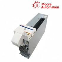
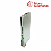
Moore Automation keeps both complete HMS designations visible throughout a paired enquiry. The W0150 and W0054 type plates are linked to separate current, mass, width and airflow fields so that the shared series prefix does not obscure the physical differences.
A cabinet photograph can show the available mounting width and the DC-bus routing. This evidence is stored with the model-specific plate images instead of being used to infer an unconfirmed system configuration.
Complete codes shown side by sidePower data stored per frameCabinet width documentedDC-bus routing kept as system evidence
Disclaimer: Moore Automation Limited is an independent reseller and is not an authorized distributor or representative of the manufacturers featured on this website. Product names and trademarks belong to their respective owners.





No related record found