Welcome to Moore Automation Limited

0
Loadding...
 

sales@mvme.cn    Phone: +86 18030175807

Home>B&R>B&R X20AI1744 / X20AI2632 X20 Analog Input Modules
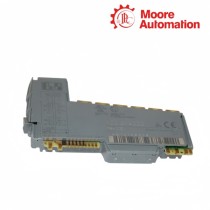
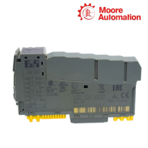
B&R X20AI1744 / X20AI2632 X20 Analog Input Modules

B&R X20AI1744 / X20AI2632 X20 Analog Input Modules Item NO.: 2942566

Write a Review
US$ 1.00
Quantity
Stock ( 28 )

Copy and share this link on social network or send it to your friends

Copy
Request Price & AvailabilitySend the part number and quantity. Our team will confirm stock, condition, lead time and the best quotation.
  • MOQ: 1 piece
  • International shipping
  • 1-year warranty on eligible items
  • Fast response during business hours
Product Name B&R X20AI1744 / X20AI2632 X20 Analog Input Modules
Item NO. 2942566
Weight 0.1 kg = 0.2205 lb = 3.5274 oz
Category B&R
Brand B&R
Creation Time 2026-11-19

B&R X20AI1744 / X20AI2632 X20 Analog Input Modules
AIX20 Module

ANALOG INPUT / MEASUREMENT

B&R X20AI1744 / X20AI2632 X20 Analog Input Modules

1 / 2measurement channels
01

Model Information

B&R X20AI1744 and X20AI2632 are analog input modules for the B&R X20 I/O system, but they serve different measurement chains. X20AI1744 excites and reads one full-bridge strain-gauge sensor through a 24-bit converter, while X20AI2632 converts two differential voltage or current signals with 16-bit resolution for standard process instrumentation.

A four- or six-wire bridge connects to X20AI1744 through SG VCC, SG GND and differential Input+ / Input- conductors. Unlike the externally generated process signal received by X20AI2632, X20AI1744 measures the bridge response in relation to its excitation supply and can use IIR and FIR filters to smooth the value or reject a selected interference frequency.

Each channel of X20AI2632 selects voltage or current through the terminal path and channel configuration, then passes the converted value through its configurable low-pass filter and error counters. X20AI1744 is commissioned around bridge resistance, excitation and mechanical zero, whereas X20AI2632 is commissioned around signal range, current/voltage terminals and channel-specific filtering.

02

Technical Specifications

Specification X20AI1744 X20AI2632
Brand B&R B&R
Product Name X20 Strain-Gauge Analog Input Module X20 Universal Analog Input Module
Country Austria Austria
Input Quantity 1 full-bridge input 2 differential analog inputs
Signal Type Full-bridge strain gauge ±10 V or 0–20 mA
Converter Resolution 24 bit 16 bit
Sensor / Source Wiring 4-wire or 6-wire bridge Separate voltage and current terminal paths
Sensor Supply Bridge excitation from module External transmitter or signal source
Input Filter 5 kHz converter filter plus IIR / FIR software filters 10 kHz hardware low-pass plus configurable digital filter
Diagnostic Focus Bridge line monitoring and converter state Open line in voltage mode, overload and channel error counters
Value Processing Bridge scaling and filtering Scaling, filtering and trace buffer
Trace / Oscilloscope Measurement filtering and module status Oscilloscope functions for channel data
Isolation Analog input and bridge supply isolated from bus Analog inputs isolated from bus
Operating Temperature -25 to 60°C horizontal; -25 to 50°C vertical -25 to 60°C horizontal; -25 to 50°C vertical
Required Station Parts X20BM11 and X20TB12 X20BM11 and X20TB12
Degree of Protection IP20 IP20
03

Sensor Interface Architecture

The two modules differ in what they supply to the field device and what quantity they convert.

01

Excited bridge measurement

X20AI1744 supplies the bridge and measures a differential imbalance created by strain. Excitation, bridge resistance, shield routing and mechanical preload all participate in the final value, so a zero shift is not diagnosed from the input pair alone.

02

Externally generated process signal

X20AI2632 receives an already formed voltage or current signal. The transmitter power and loop return remain outside the converter, and the channel terminal choice tells the module whether the signal is evaluated through the voltage or shunt path.

03

Wiring choice changes the test point

A bridge ohmmeter test, excitation measurement and mechanical zero are relevant to X20AI1744. A loop-current measurement or source-voltage test is relevant to X20AI2632; applying the wrong test method can disturb the sensor or produce a misleading result.

04

Filtering and Data Validation

Filtering is applied for different reasons and must be validated against the source dynamics.

01

Bridge-noise rejection

X20AI1744 uses its converter behavior and configurable IIR/FIR filters to stabilize a small bridge signal. The FIR option can target an interference frequency, while excessive smoothing can hide the mechanical change the application needs to detect.

02

Per-channel process filtering

X20AI2632 configures filtering independently per channel. The cutoff and order shape the response of the digitized value, so paired process signals can show different delay if their channel settings are not aligned.

03

Status before scaling

Both modules provide status that must be evaluated before engineering-unit scaling. Bridge-line faults, overloads or channel errors should invalidate the process value instead of being converted into a believable force, pressure or flow reading.

05

Common Product Questions

What should be recorded before replacing X20AI1744 or X20AI2632?

Record X20AI1744 bridge wiring, excitation, scaling and filter settings, or X20AI2632 channel type, terminal path, filter order and scaling before moving the application to replacement hardware.

When X20AI1744 drifts while X20AI2632 remains stable, which field conditions differ?

For X20AI1744, inspect bridge excitation, sensor resistance, mechanical preload, shield and thermal effects; for X20AI2632, inspect transmitter power, loop return and the selected voltage/current path.

Which filtering approach belongs to X20AI1744 and which belongs to X20AI2632?

X20AI1744 uses IIR/FIR options for the bridge signal, while X20AI2632 applies configurable per-channel low-pass processing; set each filter from the required signal bandwidth rather than copying one numeric setting.

Why can X20AI2632 show an open-line state when X20AI1744 shows a bridge fault?

X20AI2632 diagnoses its configured process-input path, while X20AI1744 evaluates the bridge and excitation conductors; trace the fault using the wiring architecture of the actual module.

How are unstable values separated from conversion faults on X20AI1744 and X20AI2632?

For X20AI1744 and X20AI2632, read module and channel status first, then compare raw values with the field signal; do not tune filters while a line, overload or converter diagnostic is active.

Can X20AI1744 replace X20AI2632 for a standard transmitter signal?

No. X20AI1744 is built for an excited full-bridge strain gauge, while X20AI2632 accepts differential voltage or current signals; their terminal functions and scaling paths are not interchangeable.

06

Multi-Brand Supply Scope

Moore Automation

https://www.mvme.cn

Moore Automation coordinates industrial control, instrumentation and monitoring components under one model-controlled enquiry.

PLC and I/OController and distributed I/O part numbers remain distinct in the request.
DCS hardwareSystem cards, terminals and companion items are recorded by exact model.
Drive componentsDrive and power-control items keep revision and accessory notes.
Monitoring hardwareSensor-chain and condition-monitoring parts remain linked to their system role.

No related record found

You May Also Like

Copyright © 2004–2026 www.mvme.cn. All rights reserved.

Disclaimer: Moore Automation Limited is an independent reseller and is not an authorized distributor or representative of the manufacturers featured on this website. Product names and trademarks belong to their respective owners.