

Dedicated voltage front end
X20AI4222 uses the same voltage-input architecture on all four channels. Field checks therefore focus on differential polarity, source reference, conductor continuity and whether the signal remains inside the ±10 V range.
Welcome to Moore Automation Limited


|
Copy and share this link on social network or send it to your friends
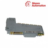
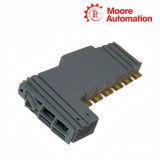
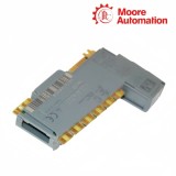
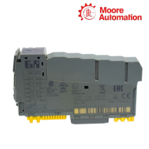
Copy| Product Name | B&R X20AI4222 / X20AI4632 X20 Analog Input Modules |
| Item NO. | 2942568 |
| Weight | 0.1 kg = 0.2205 lb = 3.5274 oz |
| Category | B&R |
| Brand | B&R |
| Creation Time | 2026-11-19 |
ANALOG INPUT / VOLTAGE AND CURRENT
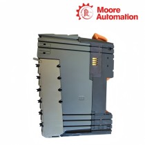
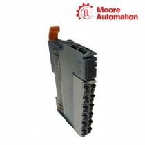
B&R X20AI4222 and X20AI4632 are four-channel differential analog input modules for the B&R X20 I/O system. X20AI4222 is dedicated to ±10 V signals with 13-bit conversion, while X20AI4632 lets each channel use either ±10 V or 0–20 mA through different terminal connections and converts the result at 16-bit resolution.
Voltage sources connect directly to the paired input terminals of X20AI4222, and its configurable filter can apply input-ramp limiting before low-pass processing to suppress short spikes. X20AI4632 adds a protected current-shunt path and channel selection, then records overload and monitoring events through channel counters and can place selected data in its trace buffer.
A cabinet migration between X20AI4222 and X20AI4632 requires more than matching the four channel numbers. Terminal positions, signal type, process scaling, filter order and accepted overload behavior must all follow the installed module, and the X20AI4632 spacing rule above 55°C must be considered with neighboring module dissipation.
| Specification | X20AI4222 | X20AI4632 |
|---|---|---|
| Brand | B&R | B&R |
| Product Name | X20 Voltage Analog Input Module | X20 Universal Analog Input Module |
| Country | Austria | Austria |
| Input Quantity | 4 | 4 |
| Signal Range | ±10 V | ±10 V or 0–20 mA |
| Converter Resolution | 13 bit | 16 bit |
| Input Type | Differential | Differential |
| Terminal Selection | Voltage input pair | Separate voltage and current terminal paths |
| Hardware Filter | Third-order low-pass, 1 kHz cutoff | Third-order low-pass, 10 kHz cutoff |
| Configurable Processing | Low-pass filter with input ramp limiting | Per-channel filter order and cutoff |
| Diagnostic Data | Overflow, underflow and channel state | Overload, error counters and channel state |
| Trace Function | Not specified | Configurable oscilloscope / trace buffer |
| Isolation | Input group isolated from bus | Input group isolated from bus |
| High-Temperature Rule | Standard mounting limits | Neighbor dissipation limit above 55°C |
| Operating Temperature | -25 to 60°C horizontal; -25 to 50°C vertical | -25 to 60°C horizontal; -25 to 50°C vertical |
| Required Station Parts | X20BM11 and X20TB12 | X20BM11 and X20TB12 |
The electrical path is fixed on one model and selectable on the other.
X20AI4222 uses the same voltage-input architecture on all four channels. Field checks therefore focus on differential polarity, source reference, conductor continuity and whether the signal remains inside the ±10 V range.
X20AI4632 routes a channel through a voltage input or current shunt according to its terminal connection and configuration. A mismatch can produce a value without representing the intended physical quantity, so wiring and software type are verified together.
The application converts the module value into engineering units after signal type and range are correct. Copying a scaling block from X20AI4222 to a current-configured X20AI4632 channel can create a numerically smooth but incorrect process value.
Each module offers a different way to control or investigate rapid changes.
X20AI4222 can limit the accepted step before the digital low-pass stage. This is useful for suppressing spikes, but the threshold must remain larger than the fastest legitimate process change or the module will reshape real events.
X20AI4632 can accumulate occurrences and resets of channel errors when the relevant counters are enabled. The count helps distinguish an intermittent wiring or range problem from a stable calibration offset.
The X20AI4632 trace buffer captures selected channel data for timing analysis. Capture configuration, channel selection and sample behavior must be documented so the recorded sequence can be compared with controller events and field measurements.
Use X20AI4632 with the documented current terminals and channel configuration; X20AI4222 is a ±10 V input module and should not be treated as a current-input replacement.
A valid indication on X20AI4222 or X20AI4632 confirms converter operation and channel status, but it does not prove correct engineering-unit scaling, transmitter calibration or terminal selection.
For X20AI4222 to X20AI4632 migration, verify the X20AI4632 voltage terminal, channel type, scaling, polarity and filter settings rather than only matching the channel number.
Read channel status and raw values on X20AI4222; on X20AI4632, also enable the relevant error counters or trace capture so brief overload or wiring events can be correlated with the process.
X20AI4632 specifies a neighboring-module dissipation limit above 55°C; keep that thermal rule with X20AI4632 even when X20AI4222 previously occupied the same slot.
X20AI4222 can apply input-ramp limiting before its filter, while X20AI4632 uses its own per-channel filter settings; compare the actual configuration before attributing the difference to hardware.
Moore Automation checks product identity, stated condition and packing scope before an order moves into shipment preparation.


Moore Automation Sales Team
Copyright © 2004–2026 www.mvme.cn. All rights reserved.
Disclaimer: Moore Automation Limited is an independent reseller and is not an authorized distributor or representative of the manufacturers featured on this website. Product names and trademarks belong to their respective owners.
No related record found