Bosch Rexroth HDS02.2-W040N-HS32-01-FW DIAX04 Digital Drive Controller
DIAX04 modular drive platform
40 A rated currentHS32 configurationFirmware separate subitem
Bosch Rexroth / HDS02.2-W040N-HS32-01-FW / DIAX04 Digital Drive Controller
SystemDIAX04
FrameHDS02.2
CoolingBuilt-in blower
01
Product Introduction
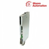
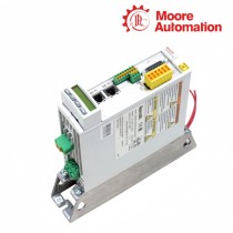
HDS02.2-W040N-HS32-01-FW is a Bosch Rexroth DIAX04 digital drive controller built around the HDS02.2 basic unit. The configured controller combines the 40 A air-cooled power section with a command-communication module, an HSM software module and any additional modules recorded in slots U1 through U4.
In HDS02.2-W040N-HS32-01-FW, the HS32 portion is the configuration identity for the control and communication arrangement, while the 01 function code and FW suffix remain part of the complete order string. The software module stores the drive firmware and parameters; the command module forms the interface to the higher-level control.
The control-cabinet boundary of HDS02.2-W040N-HS32-01-FW includes the 498 mm body length, 265 mm depth, 188 mm height and removable 56 mm contact-guard area shown in the dimensional sheet. Minimum service space is 80 mm at one end, 100 mm at the other and 90 mm below the mounting envelope.
HDS02.2 cabinet envelope with mounting rails, contact guard and minimum service space.
02
Technical Information
Attribute
HDS02.2-W040N-HS32-01-FW
Brand
Bosch Rexroth
Product type
Digital drive controller
System
DIAX04
Rated current
40 A
Peak current
40 A
Continuous current at 4 / 8 kHz
20 A / 15 A
Cooling
Internal air with built-in blower
Power loss at continuous current
125 W
Basic-unit signal-processing power
20 W
Mass
6.5 kg
Ambient with rated data
+5 to +45 °C
Derated ambient limit
+55 °C
Rated-data installation elevation
Up to 1000 m
Protection category
IP10
03
Configured HDS controller architecture
The basic unit supplies the power frame, while removable modules define communication, firmware and auxiliary signal functions.
01
HDS02.2 basic unit
HDS02.2-W040N-HS32-01-FW uses the HDS02.2-W040N basic unit as the power and cooling foundation of the configured controller. The DC-bus connection, motor power stage, terminal zone and built-in blower remain with this basic unit when the removable modules are identified separately.
02
Command communication module
The HS32 configuration in HDS02.2-W040N-HS32-01-FW identifies the command-side arrangement fitted to the basic unit. The command module is physically separate from the HSM software module and the auxiliary U slots.
03
HSM and plug-in positions
The HSM module of HDS02.2-W040N-HS32-01-FW contains firmware and drive parameters. Additional modules occupy U1–U4, and the configuration plate records which type belongs in each position.
04
Clocking, signal load and service access
Three different checks govern the configured drive: thermal clocking of the power stage, accumulated load on the signal source and physical access to guarded terminals.
Clock frequency changes continuous loading
The power stage of HDS02.2-W040N-HS32-01-FW uses a different continuous-current boundary at each permitted clock frequency because switching loss changes with the rate of commutation. The clock setting must therefore travel with the current value in commissioning records.
Slide-in modules add to the signal source
The signal source first supplies the HDS02.2 basic unit of HDS02.2-W040N-HS32-01-FW and then the command, feedback and auxiliary modules fitted to the controller. Supply sizing adds the actual U-slot population instead of assuming the bare basic-unit load is the complete requirement.
Rails, guard and cable ends define access
The mounting rails locate HDS02.2-W040N-HS32-01-FW, while the removable contact guard protects the DC-bus end and terminal area. Service space must leave room to remove the guard and route conductors without bending them into the forced-air path.
1. For HDS02.2-W040N-HS32-01-FW, which part of the designation identifies the 40 A power frame?
W040N belongs to the HDS02.2 basic unit and identifies the 40 A internal-air-cooled current class on HDS02.2-W040N-HS32-01-FW.
2. Why must the FW suffix remain in the enquiry on HDS02.2-W040N-HS32-01-FW?
For HDS02.2-W040N-HS32-01-FW, fW indicates that firmware is ordered as a separate subitem and belongs to the complete configured-controller identity.
3. HDS02.2-W040N-HS32-01-FW: Where are drive parameters stored?
With HDS02.2-W040N-HS32-01-FW, the HSM software module stores the drive firmware and parameters separately from the command-communication and auxiliary modules.
4. How are the U1–U4 modules identified for HDS02.2-W040N-HS32-01-FW?
The configuration plate records the module type assigned to each slot; COVER marks an unused position for HDS02.2-W040N-HS32-01-FW.
5. Regarding HDS02.2-W040N-HS32-01-FW, what continuous current applies at 8 kHz?
On HDS02.2-W040N-HS32-01-FW, the HDS02.2-W040N basic unit is rated for 15 A continuous at 8 kHz, compared with 20 A at 4 kHz.
6. What cabinet space is part of the dimensional boundary with HDS02.2-W040N-HS32-01-FW?
In HDS02.2-W040N-HS32-01-FW, the 498 × 265 × 188 mm device envelope is supplemented by the documented end and lower service clearances and the contact-guard area.
Moore Automation records the HDS basic unit, HS32 configuration, function code, firmware suffix and U-slot module list as separate fields. This mirrors the way the configured drive controller is assembled.
A readable configuration-plate photograph is especially useful for the U1–U4 entries and HSM type. The cabinet photo can additionally show the contact guard and mounting-rail orientation.
HDS basic unit isolatedHS32 and function code preservedHSM type entered separatelyU1–U4 slot map attached
Disclaimer: Moore Automation Limited is an independent reseller and is not an authorized distributor or representative of the manufacturers featured on this website. Product names and trademarks belong to their respective owners.





No related record found