

X20DI4371 current path
X20DI4371 completes the input through its sink circuit. The field sensor must source current into the channel, and the station reference must follow the sink connection shown for X20DI4371 rather than the source arrangement.
Welcome to Moore Automation Limited

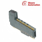
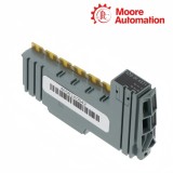
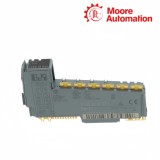

|
Copy and share this link on social network or send it to your friends
Copy| Product Name | B&R X20DI4371 / X20DI4372 X20 Digital Input Modules |
| Item NO. | 2940472 |
| Weight | 0.1 kg = 0.2205 lb = 3.5274 oz |
| Category | B&R |
| Brand | B&R |
| Creation Time | 2026-11-18 |
B&R X20DI4371 and X20DI4372 are four-channel, 24 VDC digital input modules for the B&R X20 control system. X20DI4371 and X20DI4372 receive signals from three-wire sensors and transfer the evaluated channel states to the controller, but their input circuits are designed for opposite field-current directions.
X20DI4371 uses sink inputs and therefore receives current from a sourcing sensor output, while X20DI4372 uses source inputs and expects the complementary sinking field circuit. X20DI4371 and X20DI4372 share the same terminal format and protected sensor-supply branch, but the common reference and sensor output type must match the current path of the selected module.
Filtering in X20DI4371 and X20DI4372 applies a hardware input stage before the configurable software delay generates each process value. X20DI4371 also returns four cyclic 16-bit event counters when its counter conditions are met, whereas X20DI4372 supplies the standard digital input states without those counter values.
| Specification | X20DI4371 | X20DI4372 |
|---|---|---|
| Product type | Digital input / counter module | Digital input module |
| Input quantity | 4 | 4 |
| Nominal voltage | 24 VDC | 24 VDC |
| Input circuit | Sink | Source |
| Connection type | 3-wire | 3-wire |
| Input characteristic | EN 61131-2 Type 1 | EN 61131-2 Type 1 |
| Typical input current | 3.75 mA at 24 VDC | 3.75 mA at 24 VDC |
| Hardware filter | ≤100 µs | ≤100 µs |
| Software filter | Default 1 ms; 0–25 ms in 0.2 ms steps | Default 1 ms; 0–25 ms in 0.2 ms steps |
| Input resistance | Typical 6.4 kΩ | Typical 6.4 kΩ |
| Switching thresholds | Low <5 VDC; high >15 VDC | Low <5 VDC; high >15 VDC |
| Counter functions | 4 cyclic 16-bit counters; max. 1 kHz with filters off | Not provided |
| Sensor supply | Maximum 12 W; 0.5 A summation current | Maximum 12 W; 0.5 A summation current |
| Sensor protection | Short-circuit proof; max. 2 V drop at 500 mA | Short-circuit proof; max. 2 V drop at 500 mA |
| Bus / internal I/O power | 0.14 W / 0.59 W | 0.14 W / 0.59 W |
| Isolation | 500 Veff channel group to bus | 500 Veff channel group to bus |
| Temperature | −25 to 60°C horizontal; −25 to 50°C vertical | −25 to 60°C horizontal; −25 to 50°C vertical |
| Required accessories | X20BM11 and X20TB12 ordered separately | X20BM11 and X20TB12 ordered separately |
| Pitch | 12.5 +0.2 mm | 12.5 +0.2 mm |
X20DI4371 and X20DI4372 share the same terminal format but use opposite input-current directions, so sensor output type and common reference determine which module can read the field signal.
X20DI4371 completes the input through its sink circuit. The field sensor must source current into the channel, and the station reference must follow the sink connection shown for X20DI4371 rather than the source arrangement.
X20DI4372 drives the source-side input path and expects the complementary field connection. Reusing X20DI4371 terminal positions without reviewing polarity can leave supply voltage present while no valid input current reaches X20DI4372.
Both modules fit the same X20 station parts, but that physical compatibility does not convert source wiring to sink wiring. The installed sensor output, common conductor and module order number must be recorded as one connection set.
X20DI4371 and X20DI4372 share input-delay configuration and protected sensor distribution, while only X20DI4371 adds cyclic counter data that must be handled separately in the project.
The X20DI4371 project can map its channel counters in addition to digital states. X20DI4372 should be configured only for the process data documented for that model; copying the X20DI4371 layout creates unsupported expectations.
The configurable delay is applied after the physical input stage on both modules. It should be set from the shortest valid field pulse and the measured disturbance duration, then confirmed by comparing the terminal signal with the online channel transition.
The four sensor connections use a protected supply with a combined load limit. When several sensors lose power together, inspect the shared branch and connected load before treating four channel inputs as independent electronic faults.
X20DI4371 uses sink inputs while X20DI4372 uses source inputs, so replacement requires a sensor-output and common-polarity check; the shared terminal format does not make them electrically interchangeable.
A sensor matched to the X20DI4371 sink path may not drive the X20DI4372 source path; compare the sensor output stage, 24 VDC reference and both manual connection diagrams at the terminal.
X20DI4371 documents four 16-bit event counters up to 1 kHz with filtering disabled, while X20DI4372 does not list that function; choose X20DI4371 only after confirming its sink-input wiring.
For X20DI4371 and X20DI4372, correct grounding and cable routing first, then apply the smallest 0–25 ms software delay that suppresses measured disturbance without hiding valid pulses.
X20DI4371 and X20DI4372 sensor loads must stay within 0.5 A summation current and 12 W total power, including inrush, while allowing for protection and cable voltage drop.
X20DI4371 and X20DI4372 normally use separately ordered X20BM11 bus modules and X20TB12 terminal blocks; also document sensor polarity, wiring labels, revision and quantity.
Moore Automation combines multi-brand sourcing with full-model checking and a documented enquiry-to-shipment record. The process keeps technical and commercial details visible at each handoff.
Brand, model, revision, condition and quantity are fixed in the enquiry.
Availability and commercial terms are tied to that confirmed scope.
Packing and tracking updates continue under the same order record.


Moore Automation Sales Team
Copyright © 2004–2026 www.mvme.cn. All rights reserved.
Disclaimer: Moore Automation Limited is an independent reseller and is not an authorized distributor or representative of the manufacturers featured on this website. Product names and trademarks belong to their respective owners.
No related record found