Bosch Rexroth HCS02.1E-W0054-A-03-NNNN IndraDrive C Compact Converter
IndraDrive C integrated power section
54 A maximum-current code200–500 V three-phaseNNNN design
Bosch Rexroth / HCS02.1E-W0054-A-03-NNNN / IndraDrive C Compact Converter
SeriesHCS02 IndraDrive C
Frame105 mm wide
CoolingForced ventilation
01
Product Overview
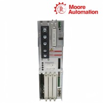
HCS02.1E-W0054-A-03-NNNN is a Bosch Rexroth IndraDrive C HCS02 compact converter for single-axis motor control. The device contains a three-phase mains rectifier, charging-current limitation, DC-bus capacitance and an inverter stage, so incoming AC power is converted into a controlled motor output within one power-section housing.
The power path through HCS02.1E-W0054-A-03-NNNN begins at X3, passes through the rectifier and soft-start circuit to L+ and L-, then reaches the inverter that supplies the motor at X5. X9 is reserved for an external braking resistor, while X6 carries motor-temperature and holding-brake connections outside the main power conductors.
The NNNN design of HCS02.1E-W0054-A-03-NNNN does not include the integrated control-voltage source shown for NNNV versions. A 24 V control supply therefore enters at X13; forced ventilation moves air through the 105 mm-wide frame, with 80 mm required above and below for the specified airflow path.
HCS02.1E-W0054/70 NNNN power path from the mains rectifier through the DC bus to the motor inverter.
02
Product Data
Attribute
HCS02.1E-W0054-A-03-NNNN
Brand
Bosch Rexroth
Product type
Compact converter
Series
IndraDrive C HCS02
Rated mains input
3 × AC 200…500 V
Nominal mains voltage
3 × AC 400 V
Rated input current
20.0 A
UL output current
20.6 A
Maximum output current at 4 kHz
54.0 A
Continuous output current at 4 kHz
20.2 A
Allowed switching frequencies
4, 8, 12, 16 kHz
Control-voltage input
24 V ±20%
Integrated braking resistor
0.35 kW continuous / 18 kW peak
Mass
6.70 kg
Housing dimensions
352 × 105 × 206 mm (H × W × D)
03
Power conversion through six defined stages
The block diagram separates each energy-handling function and shows where the external DC-bus and motor connections branch from the internal path.
01
Rectification and charging limit
At HCS02.1E-W0054-A-03-NNNN, X3 feeds the three-phase rectifier. The soft-start branch limits charging current before the DC-bus capacitors reach operating voltage, preventing the capacitors from being connected as an uncharged load without limitation.
02
DC bus and braking branch
L+ and L- expose the DC bus of HCS02.1E-W0054-A-03-NNNN for the documented common-bus arrangement. The integrated braking circuit acts on the same bus, and X9 provides the connection boundary for a permitted external braking resistor.
03
Inverter output to the motor
The inverter in HCS02.1E-W0054-A-03-NNNN draws from the DC bus and generates A1, A2 and A3 at X5. Switching frequency changes the available continuous output current, so current values must retain their frequency condition.
04
Connector groups and thermal envelope
Power, control voltage, motor auxiliaries and ventilation occupy separate physical zones on the HCS02 frame.
Front and bottom connection zones
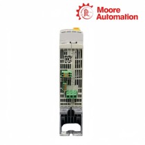
X1, X13 and the DC-bus terminals are on the front connection zone of HCS02.1E-W0054-A-03-NNNN, while X3, X5, X6 and X9 are grouped at the lower power-connection area. This separates control wiring from the main motor and mains conductors.
External 24 V path
Because HCS02.1E-W0054-A-03-NNNN carries the NNNN design, X13 receives the external 24 V control supply. The control-voltage circuit is not derived internally from the DC bus in this variant.
Forced-air clearance
The fan path of HCS02.1E-W0054-A-03-NNNN requires 80 mm at both the top and bottom of the device. The airflow allowance belongs to the complete 105 mm-wide power section, including the heat generated by continuous output current.
1. For HCS02.1E-W0054-A-03-NNNN, what does NNNN change in the control-voltage wiring?
NNNN identifies the version without the integrated control-voltage source, so an external 24 V supply is connected at X13 on HCS02.1E-W0054-A-03-NNNN.
2. Why do 54 A and 20.2 A both appear for the same converter on HCS02.1E-W0054-A-03-NNNN?
For HCS02.1E-W0054-A-03-NNNN, 54.0 A is the maximum output current at 4 kHz, while 20.2 A is the continuous output current at that switching frequency.
3. HCS02.1E-W0054-A-03-NNNN: Which terminals belong to the motor power path?
With HCS02.1E-W0054-A-03-NNNN, the inverter output reaches the motor through X5; X6 is a separate connector for motor temperature monitoring and the holding brake.
4. How is an external braking resistor connected and enabled for HCS02.1E-W0054-A-03-NNNN?
The resistor connects at X9, and its data are entered before the external-resistor function is activated in the converter configuration for HCS02.1E-W0054-A-03-NNNN.
5. Regarding HCS02.1E-W0054-A-03-NNNN, what is the role of L+ and L-?
On HCS02.1E-W0054-A-03-NNNN, l+ and L- are the DC-bus terminals between the rectifier/braking circuitry and the motor inverter, not AC mains terminals.
6. What clearance is required for forced ventilation with HCS02.1E-W0054-A-03-NNNN?
In HCS02.1E-W0054-A-03-NNNN, maintain 80 mm above and 80 mm below the housing so the specified intake and exhaust path is not obstructed.
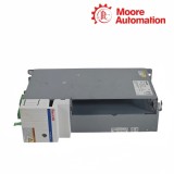
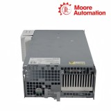
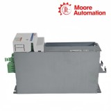
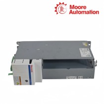
For an HCS02 enquiry, Moore Automation separates the complete device code from the connection information supplied by the customer. Photos of X3, X5, X6, X9 and the front DC-bus area can be assigned to their individual functions.
The record also distinguishes NNNN from versions with integrated control-voltage supply. This keeps the 24 V arrangement and the braking-resistor connection from being inferred from the W0054 current code alone.
Power and control terminals separatedNNNN design recorded explicitlyDC-bus photographs labeledBraking-resistor details kept distinct
Disclaimer: Moore Automation Limited is an independent reseller and is not an authorized distributor or representative of the manufacturers featured on this website. Product names and trademarks belong to their respective owners.





No related record found