Bosch Rexroth DDS02.1-W100-D DIAX02 Digital AC Servo Drive Controller
DIAX02 modular drive control
100 A peak class300 V DC busModular configuration
Bosch Rexroth / DDS02.1-W100-D / DIAX02 Digital AC Servo Drive Controller
SystemDIAX02
CoolingInternal air
ProtectionIP20
01
Product Introduction
DDS02.1-W100-D is a Bosch Rexroth digital AC servo drive controller in the DIAX02 system. The basic unit converts DC-bus energy into a controlled motor output, while the installed command-communication module, auxiliary modules and firmware define how the controller exchanges commands and processes feedback.
Inside DDS02.1-W100-D, the 300 V DC bus feeds the power section and the selected current pairing sets how peak current and continuous current are combined. The W100 air-cooled version uses either 100 A peak with 40 A continuous or 60 A peak with 60 A continuous, so the current statement must always retain the paired operating point rather than treating 100 A as a continuous rating.
Configuration data for DDS02.1-W100-D is split between the hardware configuration plate and the firmware configuration plate. The slot designations identify the command module and auxiliary plug-in modules, while the supply unit delivers the +24 V and ±15 V signal-processing rails used by the basic unit, feedback circuitry and installed modules.
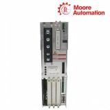
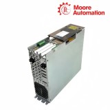
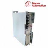
Configured DDS02.1 controller structure showing the basic unit, firmware module and plug-in positions.
02
Technical Information
Attribute
DDS02.1-W100-D
Brand
Bosch Rexroth
Product type
Digital AC servo drive controller
System
DIAX02
DC bus voltage
300 V ±15%
Peak / continuous current pairing
100 A / 40 A
Alternative peak / continuous pairing
60 A / 60 A
Basic-unit signal current at +15 V
150 mA
Basic-unit signal current at -15 V
150 mA
Basic-unit signal current at +24 V
500 mA
Rated-data ambient range
0 to +45 °C
Derated ambient limit
+55 °C
Storage and transport
-30 to +85 °C
Rated-data installation elevation
Up to 1000 m
Protection category
IP20
03
How the configured controller is assembled
The model code identifies the basic power unit; the installed modules and firmware complete the actual controller function.
01
Basic unit and power stage
DDS02.1-W100-D contains the W100 power section, the DC-bus connection and the motor-output stage in one air-cooled basic unit. The controller rating therefore belongs to the complete basic unit, not to an individual plug-in card.
02
Command communication slot
The command-communication module in DDS02.1-W100-D forms the control-side interface. Its type is recorded on the configuration plate because changing the communication module changes the controller connection boundary without changing the W100 power code.
03
Firmware and auxiliary slots
Firmware fixes the drive functions of DDS02.1-W100-D, while auxiliary modules occupy the marked U positions for additional I/O or feedback tasks. The two configuration plates keep these software and hardware identities separate.
04
How operating load moves through the configured controller
The power stage, signal rails and installed plug-in modules form separate load paths that meet only at the complete configured controller.
Peak demand and steady thermal load
The selected operating point of DDS02.1-W100-D links short-duration current headroom to a separate continuous-current boundary. Commissioning therefore keeps the documented current pair together with the connected motor instead of treating the W100 code as one universal output value.
Signal rails accumulate module load
The supply unit feeds DDS02.1-W100-D through the control-supply rails before that current is divided among the basic unit, motor-feedback circuit and installed plug-in modules. The cabinet supply calculation starts with the basic unit and then adds each fitted module on its actual rail.
Cabinet heat follows the working current
Loss in DDS02.1-W100-D changes with the motor current that the power stage carries. The power-loss curve and the permitted ambient boundary therefore work together: the curve determines heat at the operating point, while the cabinet airflow removes that heat.
1. For DDS02.1-W100-D, how can the installed configuration be checked before connecting the controller?
Read the basic-unit type plate, hardware configuration plate and firmware configuration plate together; the slot entries identify the communication and auxiliary modules actually fitted on DDS02.1-W100-D.
2. Why does the W100 designation not mean 100 A continuous current on DDS02.1-W100-D?
For DDS02.1-W100-D, the power stage pairs 100 A peak with 40 A continuous, or 60 A peak with 60 A continuous; the full current pair is the usable statement.
3. DDS02.1-W100-D: What must be included when calculating the signal-supply load?
With DDS02.1-W100-D, start with the basic-unit consumption on +24 V and ±15 V, then add the current used by motor feedback and every installed plug-in module.
4. What does a mismatch between the configuration plate and slot contents mean for DDS02.1-W100-D?
The plate is the record of which modules belong in each U position, so a mismatch means the present hardware configuration is not the recorded configuration for DDS02.1-W100-D.
5. Regarding DDS02.1-W100-D, how should cabinet heat be estimated for this controller?
On DDS02.1-W100-D, use the motor continuous current at standstill with the power-loss curve; adding only the maximum loss ignores the actual continuous load.
6. Which environmental limits apply without derating with DDS02.1-W100-D?
In DDS02.1-W100-D, the rated-data boundary is 0 to +45 °C and up to 1000 m installation elevation, with IP20 protection inside the cabinet.
For a DDS enquiry, Moore Automation records the complete basic-unit code together with the hardware and firmware configuration plates. This keeps the W100 power unit distinct from the command module and the auxiliary cards installed in its slots.
Clear photographs of all plates and the slot arrangement allow the enquiry record to preserve the controller as configured, including module suffixes that are not contained in the short base-unit designation.
Base-unit code captured separatelyHardware slot list retainedFirmware plate recordedPlate photographs attached to the enquiry
Disclaimer: Moore Automation Limited is an independent reseller and is not an authorized distributor or representative of the manufacturers featured on this website. Product names and trademarks belong to their respective owners.





No related record found