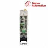
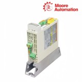
HCS01.1E-W0009-A-02-B-ET-EC-NN-L3-NN-FW is a Bosch Rexroth IndraDrive Cs HCS01 compact single-axis converter. It combines the mains-input power section and the Basic control section in one cabinet-mounted device, converting a single- or three-phase 110–230 V AC supply into a controlled three-phase motor output while the control section processes commands and feedback.
On HCS01.1E-W0009-A-02-B-ET-EC-NN-L3-NN-FW, the ET interface uses X22 and X23 for Multi-Ethernet communication, while the EC interface at X4 accepts the motor-encoder connection. These paths meet in the Basic control section, which also presents firmware-assigned digital I/O and the Bb ready-for-operation relay contact at X47.1 and X47.2.
Power for HCS01.1E-W0009-A-02-B-ET-EC-NN-L3-NN-FW enters through the mains terminals and the separate 24 V control input supplies the electronics and brake-control path. The W0009 housing belongs to the 50 mm-wide group, requires 90 mm free space above and below, and uses the standard mounting geometry shown beside this description.
Standard mounting geometry shared by the HCS01.1E-W0009 housing group.
02
Technical Specifications
Attribute
HCS01.1E-W0009-A-02-B-ET-EC-NN-L3-NN-FW
Brand
Bosch Rexroth
Product type
Compact single-axis converter
Series
IndraDrive Cs HCS01
Rated power input
1 or 3 × AC 110…230 V
Input-voltage tolerance
±10%
Mains frequency
50…60 Hz ±2 Hz
Rated input current
5.0 A single-phase / 2.3 A three-phase
Output voltage
3 × AC 0…230 V
Output current
3.0 A
Output-frequency range
0…1600 Hz
Rated control-voltage input
24 V ±20%
Mass
1.30 kg
Housing dimensions
215 × 50 × 196 mm (H × W × D)
Top / bottom clearance
90 mm / 90 mm
03
From mains input to controlled motor output
The compact housing keeps the rectifier, DC link, inverter and Basic control section inside one device boundary.
01
Input and DC-link stage
HCS01.1E-W0009-A-02-B-ET-EC-NN-L3-NN-FW accepts the -02 voltage class at the mains input. The rectifier builds the internal DC link, which becomes the electrical source for the inverter instead of feeding the motor directly from the incoming phases.
02
Inverter and motor terminals
The inverter stage in HCS01.1E-W0009-A-02-B-ET-EC-NN-L3-NN-FW switches the DC-link energy into a three-phase output at X5. Its output voltage and frequency are produced under control of the firmware and motor-feedback loop.
03
Control voltage remains separate
The 24 V input of HCS01.1E-W0009-A-02-B-ET-EC-NN-L3-NN-FW feeds the control electronics and associated low-voltage functions. It is electrically distinct from the 110–230 V power input and must be represented as a separate supply path in the cabinet wiring.
04
Communication, feedback and status paths
Three connection groups divide network data, motor feedback and hardwired operating status.
ET network ports
X22 and X23 on HCS01.1E-W0009-A-02-B-ET-EC-NN-L3-NN-FW carry the Multi-Ethernet path identified by ET. The two ports belong to the same communication function and connect the control section to the machine network.
EC encoder input
The EC option of HCS01.1E-W0009-A-02-B-ET-EC-NN-L3-NN-FW terminates the motor encoder at X4. Encoder feedback returns motor position and motion data to the control section, where it is combined with incoming commands.
Bb relay and digital I/O
The ready-for-operation state of HCS01.1E-W0009-A-02-B-ET-EC-NN-L3-NN-FW is presented through X47.1/X47.2. Firmware-assigned digital inputs and outputs provide separate hardwired signals rather than sharing the Ethernet or encoder connector.
1. For HCS01.1E-W0009-A-02-B-ET-EC-NN-L3-NN-FW, which parts of the long order code must be matched?
Match W0009, the -02 power class, B control section, ET communication, EC encoder interface, L3 safety option and the remaining NN positions as one complete designation on HCS01.1E-W0009-A-02-B-ET-EC-NN-L3-NN-FW.
2. Can the power input be wired as either single-phase or three-phase on HCS01.1E-W0009-A-02-B-ET-EC-NN-L3-NN-FW?
For HCS01.1E-W0009-A-02-B-ET-EC-NN-L3-NN-FW, the rated input is 1 or 3 × AC 110–230 V; the corresponding rated input-current value differs between the two supply arrangements.
3. HCS01.1E-W0009-A-02-B-ET-EC-NN-L3-NN-FW: Where is the device ready signal obtained?
With HCS01.1E-W0009-A-02-B-ET-EC-NN-L3-NN-FW, wire the Bb relay contact at X47.1 and X47.2 when the external control circuit needs the converter ready-for-operation state.
4. Which connector carries encoder feedback for HCS01.1E-W0009-A-02-B-ET-EC-NN-L3-NN-FW?
The EC interface places the motor-encoder connection at X4; X22 and X23 belong to the ET network path instead for HCS01.1E-W0009-A-02-B-ET-EC-NN-L3-NN-FW.
5. Regarding HCS01.1E-W0009-A-02-B-ET-EC-NN-L3-NN-FW, why must the 24 V supply be shown separately on the wiring drawing?
On HCS01.1E-W0009-A-02-B-ET-EC-NN-L3-NN-FW, the 24 V control input feeds electronics and low-voltage functions, while the mains input feeds the power-conversion stage.
6. What cabinet space must remain around the housing with HCS01.1E-W0009-A-02-B-ET-EC-NN-L3-NN-FW?
In HCS01.1E-W0009-A-02-B-ET-EC-NN-L3-NN-FW, keep 90 mm above and below the 50 mm-wide housing and use the mounting clearances shown for the W0009 frame group.
Moore Automation records the full HCS01 order code rather than reducing the enquiry to W0009. The ET, EC and L3 positions are retained because they describe different communication, feedback and safety-option boundaries.
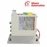
A type-plate photograph can be attached to the enquiry beside the written code. This provides a second check for punctuation, voltage class and option positions before the request is reviewed.
Full suffix string retainedType-plate image cross-checkedVoltage class separated from current classInterfaces listed by connector role
Disclaimer: Moore Automation Limited is an independent reseller and is not an authorized distributor or representative of the manufacturers featured on this website. Product names and trademarks belong to their respective owners.





No related record found