

Mounting method
Frame B and Frame C units support DIN-rail or screw mounting. The cabinet design can therefore choose the mechanical method before the incoming power and motor conductors are dressed.
Welcome to Moore Automation Limited




|
Copy and share this link on social network or send it to your friends
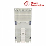
Copy| Product Name | Allen-Bradley 25C-D010N104 / 25C-D013N104 / 25C-D017N104 AC Drives |
| Item NO. | 2910973 |
| Weight | 0.1 kg = 0.2205 lb = 3.5274 oz |
| Category | AB |
| Brand | ALLEN-BRADLEY |
| Creation Time | 2026-09-24 |
Allen-Bradley 25C-D010N104, 25C-D013N104 and 25C-D017N104 are PowerFlex 527 variable-frequency AC drives for controlling three-phase induction motors in Logix-controlled machines. Installed in an electrical panel between the 380…480 V three-phase branch circuit and the motor, each drive varies motor voltage and frequency so the Logix controller can command axis speed, torque or basic position as part of the machine program.
Power entering 25C-D010N104, 25C-D013N104 and 25C-D017N104 is rectified onto the internal DC bus and switched by an IGBT inverter to the U/T1, V/T2 and W/T3 motor outputs. Motion commands, configuration, standard control data, CIP Safety data and diagnostics pass through the two embedded EtherNet/IP ports; four digital inputs, two isolated analog inputs, one analog output, two relay outputs and two opto outputs provide the hardwired signal path for local devices.
Configuration for 25C-D010N104, 25C-D013N104 and 25C-D017N104 is stored in the Logix controller and edited with Studio 5000 Logix Designer motion instructions, so the controller coordinates the speed or position command and can transfer the saved configuration to replacement hardware. An optional encoder card closes the velocity or position feedback loop when the machine requires feedback beyond the standard sensorless motor-control modes; model selection changes the available power stage and frame, not this controller-owned workflow.
| Technical Item | 25C-D010N104 | 25C-D013N104 | 25C-D017N104 |
|---|---|---|---|
| Brand | Allen-Bradley | ||
| Product type | Variable-frequency AC drive | ||
| Brand country | United States | ||
| Lifecycle | Active | ||
| Product family | PowerFlex 527 AC drive | ||
| Input | 380…480 V AC, 3-phase | ||
| Input voltage range | 323…528 V AC | ||
| Output current | 10.5 A | 13.0 A | 17.0 A |
| Normal / heavy-duty output | 4 kW / 5 HP | 5.5 kW / 7.5 HP | 7.5 kW / 10 HP |
| Frame | B | C | C |
| Enclosure | IP20 NEMA / Open Type | ||
| EMC filter | No filter | ||
| Total watts loss | 129 W | 170 W | 221 W |
| Dimensions (W × H × D) | 87 × 180 × 172 mm | 109 × 220 × 184 mm | 109 × 220 × 184 mm |
| Approximate weight | 1.6 kg (3.5 lb) | 2.3 kg (5.0 lb) | 2.3 kg (5.0 lb) |
| Motor output | 0…460 V AC, 3-phase | ||
| Control methods | V/Hz, Sensorless Vector, SVC Economizer | ||
| Controller platform | ControlLogix 1756-L7x, GuardLogix 1756-L7xS, CompactLogix 5370 | ||
| Network interface | Built-in dual-port EtherNet/IP; linear and DLR topologies | ||
| Control inputs | 4 digital; 2 independently isolated analog | ||
| Control outputs | 1 analog; 2 relay; 2 opto | ||
| Safety | Hardwired Safe Torque Off and CIP Safety over EtherNet/IP | ||
| Operating temperature | -20…+50 °C without derating | ||
| Relative humidity | 0…95% noncondensing | ||
| Altitude | 1000 m maximum without derating | ||
The three drives move from Frame B to Frame C as the output class rises, so the mounting method, cooling space and cable approach must follow the selected catalog number rather than the shared family name.
Frame B and Frame C units support DIN-rail or screw mounting. The cabinet design can therefore choose the mechanical method before the incoming power and motor conductors are dressed.
Zero stacking is permitted through a 45 °C surrounding-air limit. A hotter installation requires the spacing and derating treatment assigned to the PowerFlex 527 platform.
The front control area and lower power terminals need a service path after adjacent equipment is installed. The enclosure plan must preserve that access as the frame changes.
PowerFlex 527 operation is integrated into the Logix control project, keeping the axis command, drive configuration and replacement data within the controller environment.
The drives operate with ControlLogix 1756-L7x, GuardLogix 1756-L7xS and CompactLogix 5370 controllers. This controller list defines the supported programming architecture.
Studio 5000 Logix Designer sends embedded motion instructions to the drive. The same project environment coordinates the induction-motor axis with other machine motion.
Configuration data resides in the Logix controller. When the hardware is replaced, the controller can transfer the retained configuration to the replacement drive.
The required output current and motor power determine which of the three catalog numbers fits the axis. The frame also changes between the 10.5 A unit and the two higher-current units, so electrical sizing and cabinet fit must be checked together.
These PowerFlex 527 drives are designed for operation with supported Allen-Bradley Logix controllers. Studio 5000 motion instructions provide the command path, so the controller architecture is part of the selection.
Frame C is wider, taller, deeper and heavier than Frame B. The mounting location, conductor routing and service clearance must therefore be based on the exact model rather than a common PowerFlex 527 outline.
All three drives have embedded dual-port EtherNet/IP. The ports support linear and Device Level Ring arrangements while carrying control, diagnostic and integrated-safety traffic.
N104 identifies the IP20 open-type, standard-interface, no-filter configuration with standard braking. A filtered variant has a different catalog construction and must not be inferred from the shared current code.
The surrounding-air range reaches 50 °C without derating. Operation up to 60 °C or 70 °C uses the specified derating conditions, with the optional control-module fan required for the 70 °C case.
Moore Automation supplies industrial automation components across PLC, DCS, HMI, drive, sensor and control-system categories. The company also handles requests for current, discontinued and hard-to-find parts while keeping product identification and order communication tied to the requested catalog number.
Leonia


Moore Automation Sales Team
Copyright © 2004–2026 www.mvme.cn. All rights reserved.
Disclaimer: Moore Automation Limited is an independent reseller and is not an authorized distributor or representative of the manufacturers featured on this website. Product names and trademarks belong to their respective owners.
No related record found