

Operating indicators
RUN, forward, reverse, program and fault LEDs show the active state. Unit indicators distinguish whether the numeric display represents volts, amps, hertz or another selected value.
Welcome to Moore Automation Limited


|
Copy and share this link on social network or send it to your friends
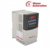
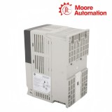
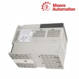
Copy| Product Name | Allen-Bradley 22A-A8P0N104 PowerFlex 4 AC Drive |
| Item NO. | 2910997 |
| Weight | 0.1 kg = 0.2205 lb = 3.5274 oz |
| Category | AB |
| Brand | ALLEN-BRADLEY |
| Creation Time | 2026-09-24 |
Allen-Bradley 22A-A8P0N104 is a PowerFlex 4 variable-frequency AC drive that converts 200…240 V single-phase input into adjustable three-phase output for a 1.5 kW / 2 HP induction motor. It is installed in the motor feeder section of a control panel and regulates motor start, stop, direction and speed from local, terminal or serial commands.
The power path in 22A-A8P0N104 runs from the input rectifier through the DC bus to an IGBT inverter and the 0…230 V motor terminals. Its four-digit display, keypad and potentiometer support local operation; fixed run terminals, two programmable inputs, one analog reference, a programmable Form C relay and RS-485 DSI connect external switches, a speed signal, status wiring or an RTU master.
Status handling in 22A-A8P0N104 begins at the four-digit display and indicator LEDs, which separate commanded direction, running state and a detected fault. Recent-fault parameters retain the diagnostic codes, the electronic overload model uses the programmed motor current, and current-limit or DC-bus supervision can alter operation or trip the drive; the larger power stage changes the mounting frame but not this operator and protection sequence.
| Technical Item | 22A-A8P0N104 |
|---|---|
| Brand | Allen-Bradley |
| Product type | Variable-frequency AC drive |
| Brand country | United States |
| Lifecycle | Discontinued June 30, 2025 |
| Product family | PowerFlex 4 AC drive |
| Input | 200…240 V AC, 1-phase |
| Input voltage range | 180…265 V AC |
| Output | 0…230 V AC, 3-phase |
| Output current | 8.0 A |
| Motor rating | 1.5 kW / 2 HP |
| Frame | B |
| Enclosure | IP20 NEMA / Open Type |
| Total power dissipation | 80 W |
| Dimensions (W × H × D) | 100 × 180 × 136 mm |
| Approximate shipping weight | 2.2 kg (4.9 lb) |
| Control method | Volts per Hertz with auto boost and slip compensation |
| Intermittent overload | 150% for 60 s; 200% for 3 s |
| Carrier frequency | 2…16 kHz adjustable |
| Digital inputs | 3 fixed and 2 programmable |
| Analog input | 1 selectable 0…10 V or 4…20 mA input |
| Output signalling | 1 programmable Form C relay |
| Communication | Integral RS-485 DSI; RTU multi-drop support |
| Operating temperature | -10…+50 °C, IP20 open type |
| Relative humidity | 0…95% noncondensing |

The front interface combines command keys, a speed potentiometer and status indication, giving one surface for local operation and parameter access.
RUN, forward, reverse, program and fault LEDs show the active state. Unit indicators distinguish whether the numeric display represents volts, amps, hertz or another selected value.
Escape, select, arrow and enter keys move through parameter groups and edit allowed values. The same display returns to read-only operating information after programming.
Start, reverse and stop keys work when the keypad is selected as the command source. The potentiometer supplies the local frequency reference when Drive Pot is active.
The drive models motor heating from current and time so the output can be interrupted before a sustained overload exceeds the configured thermal limit.
Motor OL Current is entered from the connected motor nameplate and can be set through the drive's rated-current range. That value is the base for the overload calculation.
The protection profile permits 200% loading for up to 3 seconds. A longer event moves the accumulated thermal model toward a trip.
The drive permits 150% overload for up to 60 seconds and provides Class 10 protection. Repeated loading is evaluated by the retained thermal state rather than by current magnitude alone.
The fixed keypad includes start, reverse, stop, navigation and enter functions plus a speed potentiometer. LEDs and the four-digit display identify operating state and parameter values.
It is entered from the connected motor's nameplate current, within the range allowed by the drive rating. That setting anchors the electronic Class 10 overload model.
It shows that the drive has entered a faulted state rather than simply receiving a stop command. The recent-fault display parameters identify the recorded fault code.
The drive permits the specified 150% one-minute and 200% three-second overload intervals while modelling motor heating. A condition beyond the calculated limit causes an overload trip.
The Speed Reference parameter chooses the drive potentiometer, internal frequency, analog input, preset frequency or communication port. The chosen parameter must correspond to the connected command source.
Frame B gives this 8 A model a larger outline and mass than the lower-current Frame A versions. Mounting and cable space must use the Frame B values even though the control interface looks similar.
Moore Automation presents supplied items as original products and applies inspection and packing controls before shipment. The company information provides a 12-month warranty and an after-sales communication path for product-quality questions.
 www.mvme.cn
Leonia


Moore Automation Sales Team
Copyright © 2004–2026 www.mvme.cn. All rights reserved.
Disclaimer: Moore Automation Limited is an independent reseller and is not an authorized distributor or representative of the manufacturers featured on this website. Product names and trademarks belong to their respective owners.
No related record found