

Source mode
In SRC mode, 18…24 V applied to an input is the ON state and 0…6 V is OFF. The field device supplies the positive control signal to the selected terminal.
Welcome to Moore Automation Limited



|
Copy and share this link on social network or send it to your friends
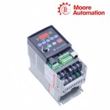
Copy| Product Name | Allen-Bradley 22A-A1P5N104 / 22A-A2P3N104 / 22A-A4P5N104 AC Drives |
| Item NO. | 2910996 |
| Weight | 0.1 kg = 0.2205 lb = 3.5274 oz |
| Category | AB |
| Brand | ALLEN-BRADLEY |
| Creation Time | 2026-09-24 |
Allen-Bradley 22A-A1P5N104, 22A-A2P3N104 and 22A-A4P5N104 are compact PowerFlex 4 variable-frequency drives for running three-phase induction motors from a 200…240 V single-phase branch. Mounted in the machine panel ahead of the motor, they provide adjustable speed, forward/reverse control and programmable acceleration or stopping for small fans, pumps, conveyors, machine tools and material-handling equipment.
In 22A-A1P5N104, 22A-A2P3N104 and 22A-A4P5N104, incoming single-phase power is rectified to the DC bus and the inverter creates 0…230 V three-phase motor output. The fixed keypad and potentiometer provide local operation; dedicated stop, start and reverse terminals, two programmable digital inputs, one isolated analog speed input, a Form C relay and integral RS-485 DSI provide the external command, reference and status paths.
Control wiring on 22A-A1P5N104, 22A-A2P3N104 and 22A-A4P5N104 uses a DIP switch to make the 24 V digital-input circuit operate as sink or source logic, and the terminal connections must follow that selection. A factory jumper completes the stop circuit for keypad operation; terminal-controlled machines replace it with the required normally closed stop path, while the motor rating selects the appropriate model within the otherwise common control arrangement.
| Technical Item | 22A-A1P5N104 | 22A-A2P3N104 | 22A-A4P5N104 |
|---|---|---|---|
| Brand | Allen-Bradley | ||
| Product type | Variable-frequency AC drive | ||
| Brand country | United States | ||
| Lifecycle | Discontinued June 30, 2025 | ||
| Product family | PowerFlex 4 AC drive | ||
| Input | 200…240 V AC, 1-phase | ||
| Input voltage range | 180…265 V AC | ||
| Output current | 1.5 A | 2.3 A | 4.5 A |
| Motor rating | 0.2 kW / 0.25 HP | 0.4 kW / 0.5 HP | 0.75 kW / 1 HP |
| Frame | A | ||
| Enclosure | IP20 NEMA / Open Type | ||
| EMC filter | No filter | ||
| Total power dissipation | 25 W | 30 W | 50 W |
| Dimensions (W × H × D) | 80 × 152 × 136 mm | ||
| Approximate shipping weight | 1.4 kg (3.1 lb) | ||
| Motor output | 0…230 V AC, 3-phase | ||
| Control method | Volts per Hertz with auto boost and slip compensation | ||
| Intermittent overload | 150% for 60 s; 200% for 3 s | ||
| Carrier frequency | 2…16 kHz adjustable | ||
| Digital inputs | 3 fixed and 2 programmable | ||
| Analog input | 1 selectable 0…10 V or 4…20 mA input | ||
| Output signalling | 1 programmable Form C relay | ||
| Communication | Integral RS-485 DSI; RTU multi-drop support | ||
| Operating temperature | -10…+50 °C, IP20 open type | ||
| Relative humidity | 0…95% noncondensing | ||
A control-logic DIP switch changes how the 24 V digital inputs are referenced, so the terminal circuit and switch position must be planned as one electrical arrangement.
In SRC mode, 18…24 V applied to an input is the ON state and 0…6 V is OFF. The field device supplies the positive control signal to the selected terminal.
In SNK mode, 0…6 V is the ON state and 18…24 V is OFF. The field circuit therefore pulls the input toward digital common rather than applying the source voltage.
A jumper between Stop and the internal 24 V point permits keypad operation in the shipped configuration. Removing it without providing the required closed stop circuit prevents the drive from starting.
Dedicated run inputs establish the basic motor commands, while programmable terminals and one active analog channel extend the operating sequence.
The Stop, Start/Run Forward and Direction/Run Reverse terminals can be assigned for two-wire or three-wire operation. The selected scheme must match the physical contact logic.
Digital Inputs 1 and 2 can select preset frequencies, jog, local control, second acceleration/deceleration, fault clearing, RS-485 control or an auxiliary fault.
Speed can follow either the 0…10 V input or the 4…20 mA input. Connecting both as simultaneous frequency references produces an undefined reference and is not a valid control arrangement.
The output current and motor rating rise from the 0.2 kW model through the 0.75 kW model. Their Frame A outline and 240 V single-phase input are shared, so motor sizing supplies the decisive difference.
The ON and OFF voltage interpretation no longer matches the field-device wiring. A command can remain inactive or behave opposite to the intended circuit until the switch and wiring method agree.
The factory jumper completes the stop circuit for keypad operation out of the box. A terminal-controlled installation replaces that jumper with the required normally closed stop path.
Only one analog frequency source is used at a time on PowerFlex 4. Simultaneous voltage and current references can produce an undetermined frequency command.
The integral RS-485 DSI connection uses its shield terminal bonded to protective earth. The serial route can support PC programming or an RTU multi-drop network.
All three use the Frame A outline of 80 × 152 × 136 mm and an approximate shipping weight of 1.4 kg. Cable bends and environmental enclosure space remain additional installation allowances.
Moore Automation uses protective packing for industrial automation components and can arrange shipment through established international couriers. Tracking information is supplied after dispatch so the shipment can be followed during transit.
Leonia



Moore Automation Sales Team
Copyright © 2004–2026 www.mvme.cn. All rights reserved.
Disclaimer: Moore Automation Limited is an independent reseller and is not an authorized distributor or representative of the manufacturers featured on this website. Product names and trademarks belong to their respective owners.
No related record found