

Separate input circuits
Main input feeds the motor-power converter, while designated control-power terminals maintain the electronics through the required supply path.
Welcome to Moore Automation Limited

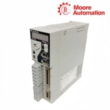

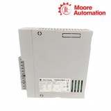

|
Copy and share this link on social network or send it to your friends
Copy| Product Name | Allen-Bradley 2071-AP0 / 2071-AP1 / 2071-AP2 Kinetix 3 Component Servo Drives |
| Item NO. | 2913759 |
| Weight | 0.1 kg = 0.2205 lb = 3.5274 oz |
| Category | AB |
| Brand | ALLEN-BRADLEY |
| Creation Time | 2026-10-09 |
Covering the 50 W, 100 W and 200 W steps of the Kinetix 3 range, the Allen-Bradley 2071-AP0 / 2071-AP1 / 2071-AP2 are standalone 230 V component servo drives that accept single-phase input and regulate one motor axis. Each drive receives motion commands through its control interfaces, processes motor feedback and delivers a separate three-phase motor output from the same compact enclosure.
At the cabinet face, 2071-AP0 / 2071-AP1 / 2071-AP2 share one physical footprint and organize incoming power, I/O, serial communication, feedback and motor connections around the drive body. Their identical dimensions simplify mounting, but the increasing output-current classes still require the motor, fuse, contactor and conductor sizes to be checked against the exact AP0, AP1 or AP2 catalog number.
| Technical Item | 2071-AP0 | 2071-AP1 | 2071-AP2 |
|---|---|---|---|
| Brand | Allen-Bradley | ||
| Product Type | Component servo drive | ||
| Series | Kinetix 3 | ||
| AC Input Voltage | 170…264 V rms, single-phase | ||
| AC Input Frequency | 47…63 Hz | ||
| Nominal Input Current | 1.30 A | 2.38 A | 3.68 A |
| Control Power Input | 170…264 V rms | ||
| Nominal Control Current | 0.1 A | ||
| Nominal DC Bus | 311 V DC | ||
| Line-Loss Ride Through | 20 ms | ||
| Bus Overvoltage / Undervoltage | 405 V DC / 190 V DC | ||
| Continuous Output Current | 0.61 A rms | 1.11 A rms | 1.72 A rms |
| Continuous Output Current, 0-pk | 0.85 A | 1.56 A | 2.40 A |
| Peak Output Current | 1.8 A rms | 3.3 A rms | 5.1 A rms |
| Peak Output Current, 0-pk | 2.55 A | 4.67 A | 7.21 A |
| Continuous Output Power | 50 W | 100 W | 200 W |
| Velocity / Current Loop Bandwidth | 550 Hz / 2000 Hz | ||
| PWM Frequency | 10 kHz | ||
| Efficiency | 90% | ||
| Short-Circuit Current Rating | 100,000 A rms symmetrical | ||
| Approximate Weight | 0.70 kg | 0.75 kg | 0.75 kg |
| Dimensions A / B / C / D | 153 / 141 / 48.3 / 53 mm | ||
| Operating Temperature | 0…50 °C | ||
| Relative Humidity | 5…95%, noncondensing | ||
The Allen-Bradley 2071-AP0 / 2071-AP1 / 2071-AP2 use three output stages to cover successive low-power motors without changing the drive’s basic single-axis architecture.
Main input feeds the motor-power converter, while designated control-power terminals maintain the electronics through the required supply path.
The inverter converts the internal DC bus into U/V/W current commanded by the drive’s position, velocity and current loops.
AP0, AP1 and AP2 increase the available motor current in line with their 50 W, 100 W and 200 W classes.
The internal bus remains charged after input removal, so service begins only after the specified discharge wait and voltage check.
The Allen-Bradley 2071-AP0 / 2071-AP1 / 2071-AP2 keep command, feedback and motor conductors on distinct interfaces so each signal follows a defined route.
Command pulses, digital inputs and status outputs use the I/O connector rather than the motor or feedback terminals.
Encoder signals return through the feedback connector or its breakout board and remain isolated from the high-current motor phases.
The serial connection supports the configured host link without occupying the discrete command terminals.
Incoming AC, control power, motor output and protective earth remain grouped at their labeled power terminals for cabinet wiring.
When specifying 2071-AP0 / 2071-AP1 / 2071-AP2, match 50 W, 100 W or 200 W output to the motor and mechanical duty. Check both continuous and peak current instead of selecting from wattage alone.
Yes. On 2071-AP0 / 2071-AP1 / 2071-AP2, the three models use the same listed body dimensions. Their input and output currents still differ, so protective devices and conductors are model-specific.
No. Before wiring 2071-AP0 / 2071-AP1 / 2071-AP2, main input supplies the motor-power converter, while the control terminals feed the electronics through their designated path. Wire and protect both as shown for the installation.
While commissioning 2071-AP0 / 2071-AP1 / 2071-AP2, it provides an orderly termination point between the motor feedback cable and drive connector. Keep encoder conductors and shield separate from motor-power wiring.
For 2071-AP0 / 2071-AP1 / 2071-AP2, not automatically. Select input protection from the exact drive’s current and the installed supply. The common enclosure size does not make their branch-circuit demand identical.
Within a 2071-AP0 / 2071-AP1 / 2071-AP2 installation, the internal DC bus can retain hazardous voltage after AC is removed. Wait at least five minutes and verify the bus has discharged before touching power terminals.
Moore Automation combines mixed-brand product availability with clear catalogue-number handling, responsive enquiry communication and coordinated international supply. Orders are built around original products and a one-year warranty rather than vague family-level substitutions.
Send the complete model and requested quantity.



Moore Automation Sales Team
Copyright © 2004–2026 www.mvme.cn. All rights reserved.
Disclaimer: Moore Automation Limited is an independent reseller and is not an authorized distributor or representative of the manufacturers featured on this website. Product names and trademarks belong to their respective owners.
No related record found