

Matched axis capacity
The smaller and larger power stages preserve the same control sequence while accommodating different motor-current demand.
LoadWelcome to Moore Automation Limited



|
Copy and share this link on social network or send it to your friends
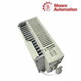
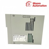
Copy| Product Name | Allen-Bradley 2071-A10 / 2071-A15 component servo drives |
| Item NO. | 2913583 |
| Weight | 0.1 kg = 0.2205 lb = 3.5274 oz |
| Category | AB |
| Brand | ALLEN-BRADLEY |
| Creation Time | 2026-10-09 |
230 V-class servo control · scalable axis current · separated control and motor paths
Allen-Bradley 2071-A10 / 2071-A15 are Kinetix 3 component servo drives that accept a 230 V-class three-phase supply and close the motor-control loop through dedicated command, encoder, and motor-power interfaces. The paired catalog numbers share the same control architecture while 2071-A15 extends the current and output capability above 2071-A10.
At the cabinet interface, 2071-A10 / 2071-A15 place mains and motor conductors on power terminals while CN1 carries command and I/O signals, CN2 returns motor feedback, and the serial connector supports commissioning communication. This separation lets the drive process position or velocity commands without routing low-level feedback through the switched motor-power path.
| Brand | Allen-Bradley | |
|---|---|---|
| Product Type | Kinetix 3 component servo drive | |
| Input Supply | 170…264 V AC, three-phase | |
| Input Frequency | 47…63 Hz | |
| Continuous Output Power | 1.0 kW | 1.5 kW |
| Continuous Output Current, RMS | 7.07 A | 9.90 A |
| Continuous Output Current, 0-pk | 9.90 A | 13.99 A |
| Peak Output Current, RMS | 18.88 A | 29.69 A |
| Peak Output Current, 0-pk | 26.70 A | 41.99 A |
| Main AC Input Current | 8.75 A | 12.37 A |
| Drive Efficiency | 90% | |
| Bus Overvoltage Level | 405 V DC | |
| Shunt Turn-off Level | 380 V DC | |
| Maximum Power Loss at 100% | 71.5 W | 93.9 W |
| Approximate Weight | 1.75 kg | |
| Operating Temperature | 0…50 °C | |
| Relative Humidity | 5…95%, noncondensing | |
| Altitude | 1000 m without derating | |
The 2071-A10 / 2071-A15 connector layout separates power conversion from command, feedback, and commissioning circuits.
Pulse, analog, enable, limit, and status signals enter the drive through the control connector.
Encoder information returns on a dedicated low-level path so the regulator can compare commanded and measured motion.
Incoming three-phase power is rectified inside the drive and controlled output leaves on the motor terminals.
Moore Automation helps identify and source discontinued industrial automation parts while keeping the complete model, suffix, quantity, and destination attached to the enquiry.


Moore Automation Sales Team
Copyright © 2004–2026 www.mvme.cn. All rights reserved.
Disclaimer: Moore Automation Limited is an independent reseller and is not an authorized distributor or representative of the manufacturers featured on this website. Product names and trademarks belong to their respective owners.
No related record found