




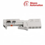

Eight-position spring-clamp wiring base
Allen-Bradley 1734-TOPS POINT I/O One-piece Terminal Base with Spring Clamp
Compact DIN-rail termination for a modular POINT I/O station.
Product Description
Designed for modular POINT I/O assemblies, the Allen-Bradley 1734-TOPS combines the mounting base with an eight-position spring-clamp wiring block. It provides the physical foundation and field connection points for a compatible POINT I/O module within the I/O row.
The narrow base interlocks with adjacent POINT I/O bases and mounts on a grounded DIN rail. Field power and signal conductors terminate at the spring-clamp block, while the side interlocks maintain alignment through the assembled station.
Because 1734-TOPS is open-style equipment, it belongs inside a suitable enclosure. Its construction includes a DIN-rail locking screw, removal handle, mechanical keying, the wiring block and interlocking side pieces, giving maintenance teams a defined mechanical interface for installation and module alignment.
Technical Specifications
| Technical Item | 1734-TOPS |
|---|---|
| Brand | Allen-Bradley |
| Product Type | POINT I/O one-piece terminal base |
| Brand Country | United States |
| Terminal Technology | Spring clamp |
| Number of Terminals | 8 |
| Dimensions (H × W × D) | 49 × 12 × 144 mm (1.93 × 0.47 × 5.67 in.) |
| Weight | 55.68 g (1.96 oz) |
| Field Power Bus Supply Voltage | 28.8 V DC; 120/240 V AC |
| Field Power Bus Supply Current | 10 A maximum |
| Signal Terminal Voltage | 28.8 V DC; 120/240 V AC |
| Signal Terminal Current | 2 A |
| Operating Temperature | -20…55 °C (-4…131 °F) |
| Nonoperating Temperature | -40…85 °C (-40…185 °F) |
| Relative Humidity | 5…95%, noncondensing |
Spring-Clamp Wiring & Conductor Preparation
Match the conductor end to the clamp
Prepare each conductor before it enters the eight-terminal spring-clamp block. The accepted cross-section and stripping length change when a ferrule is used, so one preparation cannot be applied to every wire size.
- Without ferrule: 0.25…2.5 mm² (24…14 AWG), one conductor, strip 12 mm.
- With ferrule: 0.50…0.75 mm², strip 14 mm; 1.0…1.5 mm², strip 15 mm.
- Use a 12 mm ferrule sleeve and place no more than two conductors on one terminal.
- Remove field power before inserting, removing or changing wiring.
DIN-Rail Installation & Grounding
Lock the base to a grounded steel rail
Use the specified zinc-plated, chromate-passivated steel DIN rail. The base is grounded through the rail to chassis ground, so the rail must have a reliable ground connection.
- Turn the DIN-rail locking screw to the vertical, unlocked position.
- Position the base above the installed unit and slide it down until the side pieces engage.
- Press the base onto the DIN rail, then rotate the locking screw horizontally.
- Confirm the mechanical keying before seating the POINT I/O module.
Do not remove or replace the terminal base while field-side or system-side power is applied.
Frequently Asked Questions
Can 1734-TOPS replace a screw-clamp POINT I/O base without rechecking the field wiring?
Treat the change as a terminal-technology conversion, not as an automatic wire-for-wire swap. Confirm the installed module, terminal assignment, mechanical keying and conductor preparation, then de-energize the assembly and re-terminate the conductors for the spring clamps.
Why does 1734-TOPS still move after it has been placed on the DIN rail?
Check that the side pieces are fully interlocked and that the DIN-rail locking screw has been rotated from vertical to horizontal. Also verify that the rail matches the specified steel profile and is mounted rigidly enough to provide retention and grounding.
How should ferrules be selected for mixed wire gauges on 1734-TOPS?
Match each ferrule and strip length to the conductor cross-section rather than using one preparation throughout the panel. Use the documented strip length for the selected range, keep the ferrule sleeve at 12 mm, and do not place more than two conductors on one terminal.
What must be checked before routing 120/240 V AC through 1734-TOPS?
Verify the field-power grouping and the voltage limits of the installed POINT I/O module, because the allowable system value is limited by the lower-rated component. Complete all wiring with power removed and confirm terminal assignment before energizing the field-power bus.
Can 1734-TOPS be mounted in a humid or exposed location without another enclosure?
No; it is open-style equipment and requires a suitable protective enclosure. Keep the internal environment within 5…95% relative humidity without condensation and within the specified temperature range while maintaining protection from dust, moisture and contact hazards.
How should the 10 A field-power-bus limit be handled when 1734-TOPS feeds several adjacent modules?
Add the expected downstream field current instead of assigning the full 10 A allowance to every module. Keep the calculated bus load within the terminal-base limit and within any lower current or voltage restriction imposed by the installed modules and field-power grouping.
Service Support
Moore Automation
One contact keeps each enquiry moving
An assigned account manager follows the request from the first product enquiry through quotation and order communication. This gives buyers one consistent contact for model details, commercial questions and progress updates.
Moore Automation supplies industrial automation components across PLC, DCS, TSI, HMI, drive, sensor and control-system product ranges, including current and hard-to-find parts.
Recommended Products
- Weidmüller 1478120000
- Siemens 6ES7374-2XH00-0AA0
- Weidmüller 2580230000
- Weidmüller 1918910000
- Siemens RAA21
- ABB 1SDA066409R1
- Allen-Bradley 1769-OB16
- Honeywell 34710
- Festo MC-2-1/8
- Schneider ATV12H075M2
- WAGO 750-323
- B&R X20DO9322
- Beckhoff EL6731
- Rexroth ADF134D-B05TA0-BS07-A2N1/S032
- GE CR2940U202
- Lenze MCA19S35-RS0F2
- Legrand 03842
- Brady PTL-20-7351
- ifm PK6522
- SEW MDV60A0450-503-4-0T
- SMC MXH20-15
- SICK WT27-2F410
- Weidmüller 1478110000
- Baumüller DST2-315LB54W-004-5
- Bosch LBB1950/10
- Indramat MDD093C-N-020-N2L-110GA0
- KEB 21F5A3R-YR6A
- Omron S82K-03012
- Eaton E34TB120H3X
- Finder 40.51
- Herion 2413516.2800
- Keyence MD-X2520A
- Parker D3W20BNJP30
- Phoenix Contact 2868651
- Yaskawa JUSP-0P02A
- CAREL EVD0000E20
- Krones DSC1-100S065U-10-54-AO9-DPPK-AN-O+AS1
- Danfoss 018F7658
- Lapp 4160214K
- Murr 85083
- Notifier FST-851
- Roemheld 1940201
- Aventics R481713838
- Delta DTA4896R0
- Emerson IC220PWR001D
- EMG 12-RC/10UF/100K
- Extron 70-466-11
- FISCHER 107312
- Foxboro B0123HE
- Huion HS611
- Hydac UKF-2/1.0/P+T/30/1.5/61
- Mitsubishi CL1PAD1
- Moeller NZM7-125N-M
- Motorola GMAE4507A
- Norgren F72G-3AS-001
- Pilz PAI-1NB/FBM
- PULS ML30.241
- Schunk SRU-63.2-90-3-8-R
- TRUMPF 2645891
- Wieland 93.031.3653.0
Contact Us
Send the complete part number and quantity for a quotation.


No related record found