

No mains rectifier inside the HMS01
HMS01.1N-W0020-A-07-NNNN and HMS01.1N-W0210-A-07-NNNN take DC at L+/L−. The upstream supply unit establishes the bus, so neither motor inverter should be wired as a direct three-phase mains input.
Welcome to Moore Automation Limited

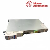
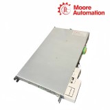

|
Copy and share this link on social network or send it to your friends
Copy| Product Name | Bosch Rexroth HMS01.1N-W0020-A-07-NNNN / HMS01.1N-W0210-A-07-NNNN IndraDrive M Motor Inverters |
| Item NO. | 2942583 |
| Weight | 0.1 kg = 0.2205 lb = 3.5274 oz |
| Category | BOSCH |
| Brand | BOSCH |
| Creation Time | 2026-11-19 |
Bosch Rexroth HMS01.1N-W0020-A-07-NNNN and HMS01.1N-W0210-A-07-NNNN are IndraDrive M motor inverters supplied from a 254–750 V DC bus. They do not contain a mains rectifier; each unit receives DC energy from the drive system and converts it into a controlled three-phase output up to 500 V for one motor axis.
HMS01.1N-W0020-A-07-NNNN is the narrow 50 mm frame with 14 A DC input and 12.1 A output, while HMS01.1N-W0210-A-07-NNNN belongs to the large-current frame with 167 A input and 151 A output. The shared -07 DC-bus class therefore describes voltage, not equal current capacity.
At the connection boundary, HMS01.1N-W0020-A-07-NNNN and HMS01.1N-W0210-A-07-NNNN receive DC at L+/L− and deliver the motor phases at X5. Their forced-air paths and continuous losses—165 W for W0020 and 1570 W for W0210—require separate cabinet placement and heat calculations.


| Attribute | HMS01.1N-W0020-A-07-NNNN | HMS01.1N-W0210-A-07-NNNN |
|---|---|---|
| 01Brand | Bosch Rexroth | Bosch Rexroth |
| 02Product type | Motor inverter | Motor inverter |
| 03Series | IndraDrive M HMS01 | IndraDrive M HMS01 |
| 04DC-bus input | DC 254…750 V | DC 254…750 V |
| 05Output voltage | 3 × AC 0…500 V | 3 × AC 0…500 V |
| 06DC input current | 14 A | 167 A |
| 07Output current | 12.1 A | 151 A |
| 08Maximum-current class | 20 A | 210 A |
| 09Control-voltage input | 24 V ±20% | 24 V ±20% |
| 10Cooling | Forced ventilation | Forced ventilation |
| 11Continuous power dissipation | 165 W | 1570 W |
| 12Nominal ambient range | 0…40 °C | 0…40 °C |
| 13Housing width | 50 mm | Large-frame drawing p131 |
| 14Mass | 5.27 kg | Model-specific large frame |
Unlike an HCS converter, each HMS01 starts at the system DC bus and is responsible only for the inverter stage of its motor axis.
HMS01.1N-W0020-A-07-NNNN and HMS01.1N-W0210-A-07-NNNN take DC at L+/L−. The upstream supply unit establishes the bus, so neither motor inverter should be wired as a direct three-phase mains input.
HMS01.1N-W0020-A-07-NNNN and HMS01.1N-W0210-A-07-NNNN switch the shared DC voltage into a controlled output at X5. Motor current is produced per axis even when several inverters share one bus.
During motor deceleration, HMS01.1N-W0020-A-07-NNNN and HMS01.1N-W0210-A-07-NNNN return energy to L+/L−. The upstream supply and braking arrangement then determine how that energy is handled.
The small and large frames perform the same inverter function but use different current-bearing parts and airflow capacity.
HMS01.1N-W0020-A-07-NNNN uses the 14 A input and 12.1 A output row; HMS01.1N-W0210-A-07-NNNN uses 167 A and 151 A. The difference is electrical, not merely a change in enclosure size.
Continuous loss rises from 165 W in HMS01.1N-W0020-A-07-NNNN to 1570 W in HMS01.1N-W0210-A-07-NNNN. Cabinet airflow must therefore be assigned from each model row.
On HMS01.1N-W0020-A-07-NNNN and HMS01.1N-W0210-A-07-NNNN, the motor phases and the temperature/brake circuits terminate at different connector groups. Their cable routes should preserve that division.
HMS01.1N-W0020-A-07-NNNN / HMS01.1N-W0210-A-07-NNNN should be recorded with this result: no. Both are motor inverters with a DC 254–750 V input at L+/L− and depend on the IndraDrive M DC-bus supply.
HMS01.1N-W0020-A-07-NNNN / HMS01.1N-W0210-A-07-NNNN: Their continuous dissipation is 165 W versus 1570 W, so the large frame requires a much larger heat-removal path.
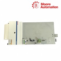
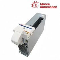
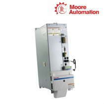
For HMS01.1N-W0020-A-07-NNNN / HMS01.1N-W0210-A-07-NNNN, provide a separate readable type plate and front/terminal photograph for each inverter so their W codes and frames cannot be exchanged.
Their input and output current rows differ sharply: 14/12.1 A for W0020 and 167/151 A for W0210. This condition belongs to HMS01.1N-W0020-A-07-NNNN / HMS01.1N-W0210-A-07-NNNN.
When checking HMS01.1N-W0020-A-07-NNNN / HMS01.1N-W0210-A-07-NNNN, it identifies the DC-bus voltage class; it does not make the two models equal in current or frame size.
The inverter output uses X5; L+/L− are the DC-bus input and must not be labeled as motor phases. Keep this requirement with HMS01.1N-W0020-A-07-NNNN / HMS01.1N-W0210-A-07-NNNN.

Moore Automation combines broad industrial-component coverage with individual enquiry handling and worldwide shipment support. The company reference material identifies inventory access, difficult-to-source part assistance and clear delivery communication as practical reasons customers use the service.
HMS01.1N-W0020-A-07-NNNN and HMS01.1N-W0210-A-07-NNNN are kept on separate rows so the narrow frame, high-current frame and their corresponding evidence remain distinguishable.
Moore Automation Sales Team
Copyright © 2004–2026 www.mvme.cn. All rights reserved.
Disclaimer: Moore Automation Limited is an independent reseller and is not an authorized distributor or representative of the manufacturers featured on this website. Product names and trademarks belong to their respective owners.
No related record found