

Input conversion remains common
HCS03.1E-W0070-A-05-NNBV and HCS03.1E-W0100-A-05-NNBV rectify the -05 mains supply before energy reaches the DC bus. The shared sequence does not make their input currents or protective devices interchangeable.
Welcome to Moore Automation Limited


|
Copy and share this link on social network or send it to your friends
Copy| Product Name | Bosch Rexroth HCS03.1E-W0070-A-05-NNBV / HCS03.1E-W0100-A-05-NNBV IndraDrive C Compact Converters |
| Item NO. | 2942575 |
| Weight | 0.1 kg = 0.2205 lb = 3.5274 oz |
| Category | BOSCH |
| Brand | BOSCH |
| Creation Time | 2026-11-19 |
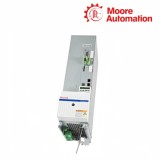
Bosch Rexroth HCS03.1E-W0070-A-05-NNBV and HCS03.1E-W0100-A-05-NNBV are IndraDrive C HCS03 compact converters for a 400–500 V three-phase mains class. Each unit combines the mains rectifier, DC bus, braking path and motor inverter, but the W0070 and W0100 power frames carry different current, conductor and heat-removal boundaries.
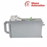
In both HCS03.1E-W0070-A-05-NNBV and HCS03.1E-W0100-A-05-NNBV, X3 receives mains power, L+ and L− expose the DC bus, and X5 supplies the motor. The W0070 uses the smaller 125 mm frame and plug-style power connection shown for its housing, while the W0100 belongs to the 225 mm frame and uses the larger screw-connection arrangement.
At 4 kHz, HCS03.1E-W0070-A-05-NNBV provides 45 A continuous output from a 70 A maximum-current frame; HCS03.1E-W0100-A-05-NNBV provides 73 A continuous output from a 100 A frame. Their 800 W and 950 W continuous dissipation figures make model-specific fuse, conductor and airflow records necessary even though the connection names are shared.


| Attribute | HCS03.1E-W0070-A-05-NNBV | HCS03.1E-W0100-A-05-NNBV |
|---|---|---|
| 01Brand | Bosch Rexroth | Bosch Rexroth |
| 02Product type | Compact converter | Compact converter |
| 03Series | IndraDrive C HCS03 | IndraDrive C HCS03 |
| 04Rated mains input | 3 × AC 400…500 V | 3 × AC 400…500 V |
| 05Rated mains current | 50 A | 80 A |
| 06Branch-circuit fuse | 63 A | 100 A |
| 07Maximum output current | 70 A | 100 A |
| 08Continuous output current at 4 kHz | 45 A | 73 A |
| 09Rated DC-bus power with choke | 25 kW | 43 kW |
| 10Minimum external braking resistance | 17.5 Ω | 11.7 Ω |
| 11Switching frequencies | 4 / 8 / 12 / 16 kHz | 4 / 8 / 12 / 16 kHz |
| 12Continuous power dissipation | 800 W | 950 W |
| 13Control-voltage input | 24 V ±20% | 24 V ±20% |
| 14Housing width | 125 mm | 225 mm |
The two converters perform the same sequence of electrical operations, while the current-bearing parts and physical frame scale with the model.
HCS03.1E-W0070-A-05-NNBV and HCS03.1E-W0100-A-05-NNBV rectify the -05 mains supply before energy reaches the DC bus. The shared sequence does not make their input currents or protective devices interchangeable.
In HCS03.1E-W0070-A-05-NNBV and HCS03.1E-W0100-A-05-NNBV, motor demand draws energy from L+/L− through the inverter, while returned energy raises the same bus and is handled through the braking path.
The W0070 stage of HCS03.1E-W0070-A-05-NNBV and the W0100 stage of HCS03.1E-W0100-A-05-NNBV use different semiconductor and thermal capacities; their 45 A and 73 A continuous values therefore remain model-specific.
Frame width is accompanied by coordinated changes in protection, connection hardware, DC-bus power and heat removal.
HCS03.1E-W0070-A-05-NNBV is paired with the 50 A input and 63 A fuse row, whereas HCS03.1E-W0100-A-05-NNBV uses the 80 A input and 100 A fuse row. The fuse change follows the power frame, not the common family name.
The compact W0070 power connection on HCS03.1E-W0070-A-05-NNBV differs mechanically from the screw-connected W0100 area on HCS03.1E-W0100-A-05-NNBV. Cable preparation must follow the drawing for the actual housing.
Continuous dissipation is 800 W for HCS03.1E-W0070-A-05-NNBV and 950 W for HCS03.1E-W0100-A-05-NNBV. Those values join the specified forced-air path in the cabinet heat calculation.
Compare values at the same switching frequency: at 4 kHz the continuous outputs are 45 A and 73 A, while the maximum-current classes are 70 A and 100 A. This condition belongs to HCS03.1E-W0070-A-05-NNBV / HCS03.1E-W0100-A-05-NNBV.
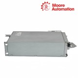
When checking HCS03.1E-W0070-A-05-NNBV / HCS03.1E-W0100-A-05-NNBV, capture the complete type plate and the power-connection area so the W code, -05 class and frame-specific terminal arrangement can be checked together.
No. The documented rows pair W0070 with 63 A and W0100 with 100 A, reflecting their different rated mains currents. Keep this requirement with HCS03.1E-W0070-A-05-NNBV / HCS03.1E-W0100-A-05-NNBV.
HCS03.1E-W0070-A-05-NNBV / HCS03.1E-W0100-A-05-NNBV should be recorded with this result: the braking circuit acts on the DC bus and X9 provides the external-resistor boundary; the minimum permitted resistance remains model-specific.
HCS03.1E-W0070-A-05-NNBV / HCS03.1E-W0100-A-05-NNBV: Their widths, power losses, input currents and conductor sizes differ, so one shared family-level record would hide installation-critical values.
For HCS03.1E-W0070-A-05-NNBV / HCS03.1E-W0100-A-05-NNBV, x3 is the mains input, X5 is the motor output, and L+/L− are the DC-bus connection on both; the mechanical termination changes with the frame.

Moore Automation assigns an account manager to coordinate each industrial automation enquiry from model review through quotation and shipment updates. The reference company material stresses clear communication, accurate lead-time information and one contact for questions throughout the process.
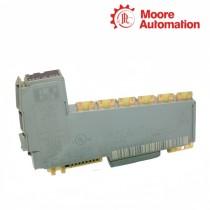
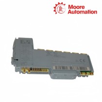
HCS03.1E-W0070-A-05-NNBV and HCS03.1E-W0100-A-05-NNBV remain separate line items, with the corresponding type-plate and frame images attached to the account record.


Moore Automation Sales Team
Copyright © 2004–2026 www.mvme.cn. All rights reserved.
Disclaimer: Moore Automation Limited is an independent reseller and is not an authorized distributor or representative of the manufacturers featured on this website. Product names and trademarks belong to their respective owners.
No related record found