




Bently Nevada · 3300 High-Pressure Feedthrough
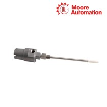
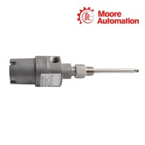
Bently Nevada 330162-03-45-45-05-05-94-01-02 3300 Dual Triaxial High-Pressure Feedthrough
Corrected official-format dual feedthrough with two independent triaxial paths
Product Description
330162-03-45-45-05-05-94-01-02 is a dual triaxial high-pressure feedthrough for two Bently Nevada 3300 proximity-transducer signal paths. Armor is fitted on the high-pressure end, and both primary cable dimensions are 4.5 m with 0.5 m high-pressure-end lead dimensions.
A fluorocarbon O-ring provides the selected sealing material for exposure to butane, fuel oil, natural gas, petroleum oil and turbine oil. Female miniature coaxial connectors face the probe side; male connectors face the Proximitor Sensor side.
The complete configuration of 330162-03-45-45-05-05-94-01-02 must remain matched to the pressure boundary and the two assigned channels. The standard assembly rating is 2.76 MPa (400 psi), and the cable-to-feedthrough interfaces must be kept away from water.
Technical Specifications
| Technical Item | 330162-03-45-45-05-05-94-01-02 |
|---|---|
| Brand | Bently Nevada |
| Product Type | Dual triaxial high-pressure feedthrough |
| Brand Country | United States |
| Armor Option | 03 — high-pressure end |
| Dimension 1 | 4.5 m |
| Dimension 2 | 4.5 m |
| Dimension 3 | 0.5 m |
| Dimension 4 | 0.5 m |
| O-Ring | 94 — fluorocarbon |
| High-Pressure Connector | 01 — female miniature coaxial |
| Low-Pressure Connector | 02 — male miniature coaxial |
| Maximum Pressure | 2.76 MPa (400 psi) |
| Operating Temperature | -26°C to +121°C (-15°F to +250°F) |
| Humidity | 100% non-condensing |
| Fitting Material | 303 stainless steel |
High-Pressure Service Limits
The feedthrough carries two triaxial cable paths through a pressurized machine case while keeping the probe-side and Proximitor-side connections correctly oriented. Fluorocarbon seals suit hydrocarbon service including natural gas, fuel oil, petroleum oil and turbine oil.
Standard service is limited to 2.76 MPa and the option-94 temperature range. The assembly can tolerate 100% non-condensing humidity, but it does not seal water away from the internal cable leads; both cable interfaces therefore need external water protection.
Feedthrough Sealing & Channel Verification
Feedthrough Sealing & Channel Verification in practice
Confirm the pressure port is 1-11 1/2 NPT on both sides and keep each signal path tagged before disconnection. Install the 303 stainless-steel fitting with the selected fluorocarbon O-ring, preserving the high-pressure and low-pressure orientation shown by the assembly geometry.
Connect the female ends to the two probes and the male ends to their assigned Proximitor Sensors. Maintain at least a 25.4 mm cable bend radius, keep every cable interface dry, and verify continuity, isolation and both monitoring-channel responses before returning the machine to service.
Frequently Asked Questions
What should maintenance personnel check first if 330162-03-45-45-05-05-94-01-02 shows leakage at the pressure boundary?
Depressurize the machine before inspection, then verify the 1-11 1/2 NPT installation, the fluorocarbon option-94 O-ring and the high-pressure/low-pressure orientation. Replace damaged sealing parts and keep external water away from both cable interfaces before returning the assembly to service.
How can crossed monitoring channels be avoided when replacing 330162-03-45-45-05-05-94-01-02?
Tag both signal paths before disconnecting them. Keep the female miniature coaxial ends on the probe side and the male ends on the Proximitor Sensor side, then prove continuity and channel response one path at a time.
What limits must be checked before using 330162-03-45-45-05-05-94-01-02 in a hotter or higher-pressure process?
The standard pressure limit is 2.76 MPa (400 psi), and option 94 defines a -26°C to +121°C operating range. Do not approve the installation from connector fit alone; both process pressure and seal temperature must remain inside these limits.
Why was the originally supplied code changed to 330162-03-45-45-05-05-94-01-02, and how does that prevent ordering errors?
The 330162 structure accepts four cable-length fields between the armor and O-ring selections. Removing the extra repeated 45 produces the valid sequence of 4.5 m, 4.5 m, 0.5 m and 0.5 m, so every following option remains in its correct position.
What should be inspected if both channels connected through 330162-03-45-45-05-05-94-01-02 become noisy?
Check for shared routing damage, water at the interfaces and bends tighter than 25.4 mm before replacing either probe. Then test continuity and isolation separately for each triaxial path and verify both Proximitor Sensor inputs.
Why Choose Moore Automation
Practical purchasing support
Inventory depth and responsive service for time-sensitive requirements
Moore Automation combines a broad automation-parts inventory with experience sourcing obsolete and hard-to-find components. This helps maintenance teams obtain replacements without changing a working control platform only because one component is difficult to locate.
Fast-delivery options, worldwide service and a one-year warranty provide additional support when downtime and purchasing risk must be controlled.



No related record found