

01
Prepared conductor
The stripped section must remain within 7 to 9 mm. Too little exposed copper prevents full insertion, while excess length leaves conductive material outside the terminal body.
Welcome to Moore Automation Limited


|
Copy and share this link on social network or send it to your friends
Copy| Product Name | B&R X20TB06 X20 6-Pin Push-In Terminal Block |
| Item NO. | 2943224 |
| Weight | 0.1 kg = 0.2205 lb = 3.5274 oz |
| Category | B&R |
| Brand | B&R |
| Creation Time | 2026-11-20 |
FIELD WIRING / PUSH-IN TERMINAL
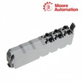
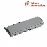
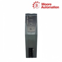
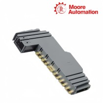
B&R X20TB06 is a six-pin, 24 VDC-keyed push-in terminal block for wiring compatible B&R X20 modules. It forms the removable field connection at the front of the module, arranging the conductors as two numbered rows of three contacts while preserving the keying of the 24 VDC station hardware.
A conductor enters X20TB06 after 7 to 9 mm of insulation is removed. The push-in spring holds solid or prepared stranded copper wire without a screw, and the release lever opens the contact for removal; the conductor size, ferrule and crimp therefore work together to maintain the documented holding force.
Planning and testing on X20TB06 use the molded row and terminal numbers rather than an unqualified six-position sequence. Each contact also has a separate 2 mm probe opening, so measurements can be taken without disturbing the field conductor, while customer coding and labeling keep the removable block assigned to the intended module.
| Brand | B&R |
|---|---|
| Product Type | X20 push-in terminal block |
| Number of Pins | 6 |
| Terminal Arrangement | 2 rows × 3 numbered contacts |
| Keying | 24 VDC |
| Connection Method | Push-in spring terminal |
| Conductor Material | Copper only |
| Single-Wire Range | 0.08 to 2.50 mm² / 28 to 14 AWG |
| Fine-Stranded Range | 0.25 to 2.50 mm² / 24 to 14 AWG |
| Ferruled Wire Range | 0.25 to 1.50 mm² / 24 to 16 AWG |
| Double Ferrules | Up to 2 × 0.75 mm² |
| Wire Stripping Length | 7 to 9 mm |
| Nominal Voltage | 240 VAC / 48 VDC |
| Maximum Voltage | 300 VAC / 60 VDC |
| Nominal Current | 10 A per contact, subject to module limits |
| Contact Resistance | ≤5 mΩ |
| Test-Probe Opening | 2 mm per contact |
| Push-In Force | Typically 10 N per contact |
Secure X20TB06 wiring depends on the relationship between stripping length, conductor preparation and the spring contact.
The stripped section must remain within 7 to 9 mm. Too little exposed copper prevents full insertion, while excess length leaves conductive material outside the terminal body.
A solid wire or correctly crimped ferrule is pushed to the end of the contact path, where the spring applies the holding force. Fine-stranded wire must be twisted or ferruled so individual strands do not fold outside the clamp.
The lever opens the spring before the conductor is withdrawn. Pulling against the closed contact can damage the terminal or reduce the cable retention expected from the selected wire size.
The molded identifiers and dedicated probe openings let X20TB06 remain traceable during assembly, measurement and replacement.
The upper molded digit identifies row 1 or 2 and the lower digit identifies terminal 1 to 3. Wiring drawings can therefore refer to one unambiguous physical contact.
The 2 mm test opening reaches the same electrical contact without using the conductor entry. A standard probe can check a signal while the field wire remains fully seated.
Customer coding limits accidental reassignment of a removable block, while terminal and plain-text labels relate the physical connector to the documented channel or potential.
Each X20TB06 contact uses two molded numbers: the upper number is row 1 or 2 and the lower number is terminal 1, 2 or 3. Use both numbers in the wiring schedule.
For X20TB06, confirm 7 to 9 mm stripping length, an allowed copper-wire cross section and full insertion to the stop. Fine-stranded conductors should be twisted or fitted with a correctly crimped ferrule.
The 10 A value is the contact rating of X20TB06. The lower limit of the installed X20 module, conductor, common terminal or potential group still governs the finished circuit.
Exposed parts of a disconnected X20TB06 can remain live. Do not work on the disconnected terminal block at voltages starting at 50 V; isolate and verify the circuit first.
No. X20TB06 is specified for copper conductors only. Select a compatible copper conductor and termination method within the documented cross-section range.
Yes. Every X20TB06 contact provides a separate 2 mm probe opening. Insert the test probe there so the field conductor remains clamped in its push-in connection.
Moore Automation separates the electronic module from its removable terminal and other required station parts when confirming a supply list.
Moore Automation Sales Team
Copyright © 2004–2026 www.mvme.cn. All rights reserved.
Disclaimer: Moore Automation Limited is an independent reseller and is not an authorized distributor or representative of the manufacturers featured on this website. Product names and trademarks belong to their respective owners.
No related record found