

01
I/O-only potential group
X20PS2100 starts a new internal I/O supply group on its power-supply bus module. Field-side energy continues to the modules on its right while X2X Link power must already exist elsewhere in the station.
Welcome to Moore Automation Limited


|
Copy and share this link on social network or send it to your friends
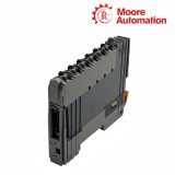
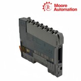
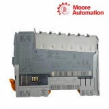
Copy| Product Name | B&R X20PS2100 / X20PS3300 / X20PS9402 X20 Power Supply Modules |
| Item NO. | 2943225 |
| Weight | 0.1 kg = 0.2205 lb = 3.5274 oz |
| Category | B&R |
| Brand | B&R |
| Creation Time | 2026-11-20 |
POWER DISTRIBUTION / X20 SYSTEM
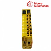
B&R X20PS2100, X20PS3300 and X20PS9402 are 24 VDC supply modules for different power boundaries in the B&R X20 system. X20PS2100 feeds only the internal I/O supply, X20PS3300 feeds both the X2X Link and internal I/O rails, and X20PS9402 is paired with an X20 bus controller to feed that controller, X2X Link and the internal I/O supply in a compact station.
With X20PS2100, the incoming 24 VDC passes through the terminal and external line fuse to the I/O potential group; the module monitors the supply limits but does not create a separate X2X Link feed. X20PS3300 separates the protected X2X Link input from the I/O input, so two supplies can remain isolated, while the documented jumper arrangement permits one supply to feed both paths when the installation is designed that way.
The connection arrangement for X20PS9402 resembles a combined bus-controller station feed, but its controller/X2X output is not galvanically isolated from its input and cannot be expanded or operated redundantly with additional X20PS3300 or X20PS3310 modules. Selection between X20PS2100, X20PS3300 and X20PS9402 is therefore determined by which rails must be powered, whether isolation or redundancy is required, and whether the supply belongs to a standard potential group or a bus-controller base.
| Product Role | Internal I/O supply | X2X Link and internal I/O supply | Bus controller, X2X Link and internal I/O supply |
|---|---|---|---|
| Input Voltage | 24 VDC -15% / +20% | 24 VDC -15% / +20% | 24 VDC -15% / +20% |
| X2X Link Output | Not provided | 7 W nominal | 7 W with temperature-dependent derating |
| X2X Input Protection | Not applicable | Integrated, non-replaceable fuse; reverse-polarity protection | Integrated, non-replaceable fuse; reverse-polarity protection |
| I/O Input Fuse | External max. 10 A slow-blow | External max. 10 A slow-blow | External max. 10 A slow-blow |
| I/O Contact Load | 10 A | 10 A | 10 A |
| X2X Supply Isolation | Not applicable | Isolated from X2X input | Not isolated from controller/X2X input |
| Parallel Connection | Not applicable | Permitted for X2X supply | Not permitted |
| Redundant Operation | Not applicable | Permitted for X2X supply | Not permitted |
| Bus Module / Base | X20BM01 or X20BM05 | X20BM01 or X20BM05 | X20BB80, X20BB81 or X20BB82 |
| Terminal Block | X20TB12 | X20TB12 | X20TB12 |
| Status and Diagnostics | Operating state and module status | Overload, operating state and module status | Operating state, overload and module status |
| Horizontal Operation | -25 to 60°C | -25 to 60°C | Output derating applies above stated load temperature |
| Vertical Operation | -25 to 50°C | -25 to 50°C | Output derating applies above stated load temperature |
These three modules differ most clearly in which internal rails receive energy after 24 VDC reaches the terminal.
X20PS2100 starts a new internal I/O supply group on its power-supply bus module. Field-side energy continues to the modules on its right while X2X Link power must already exist elsewhere in the station.
X20PS3300 accepts a protected input for the X2X Link and a separately fused input for I/O power. Keeping those conductors separate preserves the electrical isolation designed between the bus supply and its source.
X20PS9402 distributes one station supply to the bus controller/X2X path and the I/O path on the matching bus base. It is intended for the defined small-system topology rather than a supply chain expanded with bus transmitters.
The connection diagrams show that a shared 24 V source and a redundant X2X arrangement are different design choices.
A documented jumper can make one 24 V source serve both input paths on X20PS3300. The jumper changes the source relationship, so the installation no longer has two isolated external supplies even though the internal rail organization remains defined.
Multiple X20PS3300 modules can support a redundant X2X supply. The I/O potential groups still follow their own 10 A contact and external fuse boundaries; redundancy of the bus rail does not duplicate field-load protection.
X20PS9402 does not allow parallel or redundant controller/X2X output. A design that needs additional X2X power, bus-transmitter expansion or redundancy must use a supply topology that explicitly supports those functions.
Use X20PS2100 when the station already has X2X Link power and only the internal I/O supply must begin at that position. X20PS3300 adds an X2X feed, while X20PS9402 belongs to a bus-controller base.
When X20PS3300 uses the documented jumper arrangement, retain the external slow-blow protection for the I/O path and the correct terminals for X2X and I/O inputs. The jumper does not remove the separate internal functions.
X20PS3300 monitors the X2X supply path separately from the I/O path. Check the protected X2X input, connected bus load and overload status instead of assuming the field I/O voltage proves that both rails are healthy.
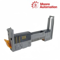
X20PS9402 mounts with an X20BB80, X20BB81 or X20BB82 bus-controller base, whereas X20PS2100 and X20PS3300 use X20BM01 or X20BM05 power-supply bus modules. All three use an X20TB12 terminal block.
No. X20PS9402 does not support expansion or redundancy of its bus-controller/X2X supply with X20PS3300 or X20PS3310. Select the station topology before wiring the supply modules.
X20PS2100 needs a power-supply bus module that interrupts the internal I/O supply to the left. That interruption defines the start of the new potential group supplied to modules on the right.
Moore Automation records modules, bases, terminal blocks and companion accessories as separate line items within one reviewed supply scope.


Moore Automation Sales Team
Copyright © 2004–2026 www.mvme.cn. All rights reserved.
Disclaimer: Moore Automation Limited is an independent reseller and is not an authorized distributor or representative of the manufacturers featured on this website. Product names and trademarks belong to their respective owners.
No related record found