

01
Transmit buffer
The controller supplies an identifier, payload length and up to eight data bytes. X20CS1070 accepts the complete object into its internal buffer before placing the corresponding CAN frame on the field network.
Welcome to Moore Automation Limited

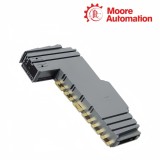
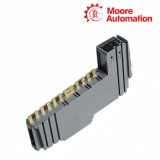
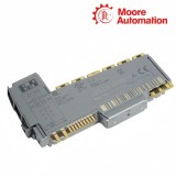

|
Copy and share this link on social network or send it to your friends
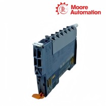
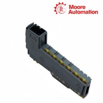
Copy| Product Name | B&R X20CS1070 X20 CAN Communication Module |
| Item NO. | 2943227 |
| Weight | 0.1 kg = 0.2205 lb = 3.5274 oz |
| Category | B&R |
| Brand | B&R |
| Creation Time | 2026-11-20 |
CAN COMMUNICATION / REMOTE MODULE
B&R X20CS1070 is a single-interface CAN communication module for the B&R X20 I/O system. Positioned like a standard X20 electronics module at a remote X2X or POWERLINK station, X20CS1070 lets the controller send and receive application-defined CAN objects without reserving a controller expansion slot.
A CAN frame handled by X20CS1070 consists of a four-byte identifier field and up to eight data bytes. Transmit objects enter the module buffer from cyclic registers or Flatstream, and received objects are stored with their identifiers before the controller accepts them; configurable filters decide which incoming CAN identifiers are forwarded or discarded.
The field connection of X20CS1070 uses CAN high, CAN low and CAN ground on an X20TB06 or X20TB12 terminal block. The CAN circuit is isolated from the bus and I/O supply, an integrated resistor can terminate the segment, and Tx, Rx and termination indicators show whether the communication path is sending, receiving or physically ended at the module.
| Brand | B&R |
|---|---|
| Product Type | X20 CAN communication module |
| CAN Interfaces | 1 |
| Maximum Transfer Rate | 1 Mbit/s |
| Maximum Segment Distance | 1000 m |
| CAN Payload | 0 to 8 bytes per object |
| Identifier Field | 4-byte internal representation; 11-bit or 29-bit CAN identifier |
| Internal Buffer | Up to 18 CAN objects |
| Stream Filters | Up to 4 per interface |
| Transfer Methods | Cyclic registers or Flatstream |
| Termination | Integrated, switchable |
| Electrical Isolation | CAN isolated from bus and I/O supply |
| Status Indication | Module, Tx, Rx and termination |
| Bus Module | X20BM11; X20BM15 optional for node switch |
| Terminal Block | X20TB06 or X20TB12 |
| Operating Temperature | -25 to 60°C horizontal; -25 to 50°C vertical |
X20CS1070 separates the fieldbus frame from its transport across the X20 station.
The controller supplies an identifier, payload length and up to eight data bytes. X20CS1070 accepts the complete object into its internal buffer before placing the corresponding CAN frame on the field network.
Incoming CAN frames are stored together with their identifiers. The controller reads the received object and acknowledges its transport, keeping field timing separate from the controller task that consumes the message.
Up to four ordered filters compare configured identifier and mask bits. The first matching rule decides whether a frame is forwarded or ignored; a global action handles frames that match none of the rules.
The selected function model determines how CAN objects cross the bandwidth-limited X2X or POWERLINK process image.
The Flat model exposes cyclic registers for one defined object relationship at a time. It suits controller logic that directly writes identifier, length and data fields without a segmented stream protocol.
Flatstream divides a longer sequence of CAN objects into transport segments that fit the enabled Tx and Rx byte registers. Sequence and acknowledgement counters prevent the sender from overwriting a segment before the receiver accepts it.
X2X and POWERLINK retain last valid values during certain communication disturbances. Because that behavior can delay a CAN telegram, application logic must evaluate the Flatstream sequence state rather than treating unchanged bytes as a newly received object.
Use Flatstream on X20CS1070 when the application must move a sequence of CAN objects through a defined set of cyclic Tx and Rx bytes. Configure and monitor the sequence and acknowledgement counters with the selected MTU.
For X20CS1070 with Flatstream, evaluate InputSequence, OutputSequence and their acknowledgements before accepting the bytes as a new message. Last valid transport values can remain visible during a network disturbance.
Check the ordered stream filters on X20CS1070. The first matching mask and identifier rule controls the frame, and the default action applies when no rule matches; a broader earlier filter can prevent a later rule from being reached.
The termination LED on X20CS1070 indicates only that its internal resistor is enabled. A module located inside the segment should leave that resistor off and rely on termination at the two actual ends.
For X20CS1070, provide the CAN identifier, the payload length and zero to eight payload bytes as one complete object. The module moves the object to its transmit buffer only after the frame data is complete.
X20CS1070 uses an X20BM11 bus module and an X20TB06 or X20TB12 terminal block, ordered separately. X20BM15 can be used when the station arrangement requires its node-number switch.
Moore Automation keeps connection, protocol and accessory questions attached to the original model enquiry rather than separating them from the requested part.
Moore Automation Sales Team
Copyright © 2004–2026 www.mvme.cn. All rights reserved.
Disclaimer: Moore Automation Limited is an independent reseller and is not an authorized distributor or representative of the manufacturers featured on this website. Product names and trademarks belong to their respective owners.
No related record found