

01
Mechanical seating
The 25 mm base occupies two standard X20 pitches so a matching double-width I/O module can lock to one continuous foundation instead of spanning two unrelated bases.
Welcome to Moore Automation Limited


|
Copy and share this link on social network or send it to your friends
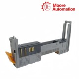
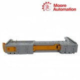
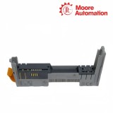
Copy| Product Name | B&R X20BM21 X20 Double-Width Power Supply Bus Module |
| Item NO. | 2943221 |
| Weight | 0.1 kg = 0.2205 lb = 3.5274 oz |
| Category | B&R |
| Brand | B&R |
| Creation Time | 2026-11-20 |
BUS FOUNDATION / VOLTAGE GROUP
B&R X20BM21 is a 24 VDC-keyed power-supply bus module for double-width I/O modules in the B&R X20 system. It provides the mechanical base and internal bus connection for the installed module while creating a defined break in the internal I/O supply on its left side.
Inside X20BM21, the X20 backplane path continues through the double-width station position, but the field-side +24 VDC and ground conductors do not pass in from the module on the left. The supply introduced at this position is routed to the right, which prevents the new potential group from borrowing field power from the preceding section.
When an X20BT9100 bus transmitter supplies the station, X20BM21 forms the base used to start that separate voltage group. The downstream load must remain within the 10 A contact boundary, and the 25 mm pitch must be reserved for the double-width module and its terminal arrangement.
| Brand | B&R |
|---|---|
| Product Type | X20 power-supply bus module |
| Supported Module Width | Double-width X20 I/O modules |
| Keying | 24 VDC |
| Primary Function | Creates a separate internal I/O voltage group |
| Left-Side I/O Supply | Interrupted |
| Right-Side I/O Supply | Routed from the supply introduced at this station |
| Nominal I/O Voltage | 24 VDC |
| Permissible Contact Load | 10 A |
| Bus Power Consumption | 0.13 W |
| Mechanical Pitch | 25 +0.2 mm |
| Mounting Orientation | Horizontal or vertical |
| Protection Rating | IP20 |
| Horizontal Operating Temperature | -25 to 60°C |
| Vertical Operating Temperature | -25 to 50°C |
| Installation Elevation | 0 to 2000 m without limitation |
X20BM21 combines the mechanical seating, bus contacts and 24 VDC keying needed by a double-width X20 station position.
The 25 mm base occupies two standard X20 pitches so a matching double-width I/O module can lock to one continuous foundation instead of spanning two unrelated bases.
Bus contacts carry X20 communication and electronics power across the station position. The field-power break is therefore separate from continuity of the internal X20 bus.
The 24 VDC keying aligns the installed module and terminal arrangement with the intended supply class, helping prevent a differently keyed station component from being treated as interchangeable.
The defining electrical behavior of X20BM21 is where the internal I/O supply stops and where the next voltage group begins.
The +24 VDC and ground route from the left ends at the X20BM21 boundary. Loads mounted to the right cannot draw field power until a supply is introduced for the new group.
A double-width supply arrangement such as X20BT9100 injects the field potential at this base. X20BM21 then carries that potential onward through the right-hand I/O contacts.
Every module in the new group contributes to the current passing through the bus-module contacts. The total downstream load must be counted against the 10 A contact rating rather than evaluated one module at a time.
No. X20BM21 is selected specifically when the field-side I/O supply must be separated from the section on the left. A pass-through application requires the bus-module type defined for continuous I/O power.
Add the field current of all modules supplied through the right side of X20BM21. The combined routed current must stay within the 10 A contact load and within the limits of the supply module and conductors.
The 25 mm pitch of X20BM21 is reserved for one double-width X20 module. Do not plan it as two independent 12.5 mm module positions, because the mechanical and electrical base is one unit.
X20BM21 intentionally interrupts the internal I/O supply from the left. Verify that the double-width supply arrangement at this position is energized and that +24 VDC and ground are present for the new group.
The X20BM21 wiring graphic shows +24 VDC and ground leaving the base to the right without a corresponding feed from the left. That routing distinguishes it from a bus module with continuous I/O power.
On X20BM21, the internal X20 bus path and the interrupted I/O supply are different circuits. Communication can continue through the base even when the new 24 VDC field-potential group has not been energized.
Moore Automation keeps the requested bus module, installed module width and related supply components together during enquiry review.


Moore Automation Sales Team
Copyright © 2004–2026 www.mvme.cn. All rights reserved.
Disclaimer: Moore Automation Limited is an independent reseller and is not an authorized distributor or representative of the manufacturers featured on this website. Product names and trademarks belong to their respective owners.
No related record found