

01
Assigned pulse source
A pulse output supplies the external contact circuit and the safe input reads the returned pattern. A missing or unexpected pattern gives the module more information than a constant 24 V signal alone.
Welcome to Moore Automation Limited



|
Copy and share this link on social network or send it to your friends
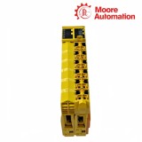
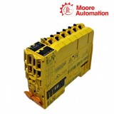
Copy| Product Name | B&R X20SI4100 / X20SI8110 X20 Safe Digital Input Modules |
| Item NO. | 2943228 |
| Weight | 0.1 kg = 0.2205 lb = 3.5274 oz |
| Category | B&R |
| Brand | B&R |
| Creation Time | 2026-11-20 |
SAFEIO / SENSOR EVALUATION
B&R X20SI4100 and X20SI8110 are 24 VDC type A safe digital input modules in the B&R X20 SafeIO system. X20SI4100 provides four safe inputs with four pulse outputs in a double-width format, while X20SI8110 places eight safe inputs and four pulse outputs in a single-width station position; both transfer evaluated sensor states to the SafeLogic application.
Sensor wiring on X20SI4100 or X20SI8110 can return a contact or electronic sensor signal directly or combine it with an assigned diagnostic pulse. The module compares the received state with the configured channel behavior, detects defined line faults, and applies separate switch-on and switch-off filters so a rising transition and a falling transition can be delayed independently.
The four pulse sources on X20SI4100 can be assigned closely to its four input circuits, whereas the eight inputs on X20SI8110 share four pulse outputs across a denser terminal arrangement. Both modules require safety-keyed station parts, isolate the input group from the X20 bus but not channel from channel, and add the selected filter time to the safe input update path.
| Safe Digital Inputs | 4 type A | 8 type A |
|---|---|---|
| Pulse Outputs | 4 push-pull | 4 push-pull |
| Mechanical Format | Double-width, 25 mm pitch | Single-width, 12.5 mm pitch |
| Nominal I/O Voltage | 24 VDC | 24 VDC |
| Voltage Range | 24 VDC -15% / +20% | 24 VDC -15% / +20% |
| Input Circuit | Sink | Sink |
| Input Standard | EN 61131-2 Type 1 | EN 61131-2 Type 1 |
| Hardware Input Filter | ≤150 µs | ≤150 µs |
| Software Filter | 0 to 500 ms | 0 to 500 ms |
| Input Error Detection Time | 100 ms | 200 ms |
| Line Length | 60 m unshielded / 400 m shielded | 60 m unshielded / 400 m shielded |
| Channel-to-Bus Isolation | Yes | Yes |
| Channel-to-Channel Isolation | No | No |
| Minimum Bus Cycle | 800 µs | 800 µs |
| Maximum I/O Update | 1750 µs + configured filter | 1750 µs + configured filter |
| Required Bus Module | X20BM33 or X20BM36 | X20BM13 or X20BM16 |
| Required Terminal Block | X20TB52 | X20TB52 |
| Operating Temperature | 0 to 60°C horizontal; 0 to 50°C vertical | 0 to 60°C horizontal; 0 to 50°C vertical |
The input and pulse channels form one diagnostic path when line-fault detection is required for a contact-based sensor.
A pulse output supplies the external contact circuit and the safe input reads the returned pattern. A missing or unexpected pattern gives the module more information than a constant 24 V signal alone.
Independent inputs can evaluate separate devices, while paired inputs can represent one two-channel sensor with equivalent or antivalent states. The safety application defines the required channel relationship.
An OSSD sensor already generates diagnostic test gaps. Its wiring mode and switch-off filter must preserve those signals correctly instead of adding a pulse source that the sensor was not designed to accept.
X20SI4100 and X20SI8110 use the same safe-input principle but organize terminals and pulse resources differently.
Filter-on delays a rising edge and filter-off delays a falling edge. The selected values suppress only the intended disturbance and become part of the calculated response time.
X20SI4100 pairs four inputs with four pulse outputs across a double-width base. The one-to-one pulse availability simplifies separate diagnostic circuits when cabinet width is less restrictive.
X20SI8110 doubles the input count in a single-width position while retaining four pulse outputs. Circuit planning must show which inputs share those diagnostic sources and how the denser terminal assignment is divided.
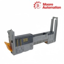
No. Double-width X20SI4100 uses a safety-keyed X20BM33 or X20BM36, while single-width X20SI8110 uses X20BM13 or X20BM16. Confirm the base before assembling the station.
X20SI8110 provides eight safe inputs in one single-width position. Two X20SI4100 modules also total eight inputs but require two double-width bases and provide eight pulse outputs rather than four.
On X20SI8110, document which input circuits use each Pulse 1 to Pulse 4 source. Inputs can share a diagnostic pulse only when the wiring and fault-detection requirements of the selected safety function permit it.
Synchronous channel blinking on X20SI8110 indicates a dual-channel evaluation error. Inspect the paired sensor states, discrepancy behavior, pulse wiring and configured equivalent or antivalent relationship.
An electronic OSSD sensor supplies its own diagnostic pattern. Configure X20SI4100 for the documented electronic-sensor connection and use the switch-off filter to handle permitted test gaps instead of imposing an incompatible external pulse.
X20SI4100 applies the configured filter-on or filter-off time before updating the evaluated state. Compare the selected edge filter and safety response calculation before treating the delay as a network fault.
Moore Automation records safety modules, keyed bus bases and terminal blocks as separate confirmed items so the requested station arrangement remains visible.


Moore Automation Sales Team
Copyright © 2004–2026 www.mvme.cn. All rights reserved.
Disclaimer: Moore Automation Limited is an independent reseller and is not an authorized distributor or representative of the manufacturers featured on this website. Product names and trademarks belong to their respective owners.
No related record found