


Welcome to Moore Automation Limited

0
Loadding...
 

sales@mvme.cn    Phone: +86 18030175807

Home>B&R>B&R X20DO4321 / X20DO4529 X20 Digital Output Modules
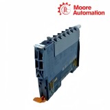
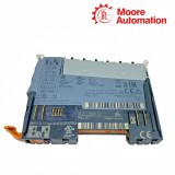
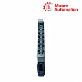
B&R X20DO4321 / X20DO4529 X20 Digital Output Modules

B&R X20DO4321 / X20DO4529 X20 Digital Output Modules Item NO.: 2942560

Write a Review
US$ 1.00
Quantity
Stock ( 28 )

Copy and share this link on social network or send it to your friends

Copy
Request Price & AvailabilitySend the part number and quantity. Our team will confirm stock, condition, lead time and the best quotation.
  • MOQ: 1 piece
  • International shipping
  • 1-year warranty on eligible items
  • Fast response during business hours
Product Name B&R X20DO4321 / X20DO4529 X20 Digital Output Modules
Item NO. 2942560
Weight 0.1 kg = 0.2205 lb = 3.5274 oz
Category B&R
Brand B&R
Creation Time 2026-11-19

B&R X20DO4321 / X20DO4529 X20 Digital Output Modules
DOX20 Module

DIGITAL I/O / OUTPUT TECHNOLOGIES

B&R X20DO4321 / X20DO4529 X20 Digital Output Modules

4outputs per module
01

Model Information

B&R X20DO4321 and X20DO4529 are four-channel digital output modules for the B&R X20 I/O system, but they control field loads through different output stages. X20DO4321 uses 24 VDC low-side semiconductor outputs for rapid cyclic actuator control, while X20DO4529 uses four isolated changeover relays to switch AC or DC circuits through NC, COM and NO contacts.

Field current for X20DO4321 enters through the 24 VDC actuator supply and returns through each sink output when its channel is enabled; the module monitors the commanded and actual output state and thermally protects the FET stage. In X20DO4529, the X20 logic energizes a relay coil and the field circuit remains electrically separate on the contact side, so the load supply, contact protection and conductor routing are provided outside the module.

Installation of X20DO4321 therefore centers on correct 24 VDC polarity, shared actuator-supply limits and three-wire terminal assignments, whereas X20DO4529 requires the correct NC/COM/NO path and an external suppression network selected for the connected AC or DC load. Both modules use an X20BM11 bus module and X20TB12 terminal block ordered separately.

02

Technical Specifications

Specification X20DO4321 X20DO4529
Brand B&R B&R
Product Name X20 Digital Output Module X20 Relay Output Module
Country Austria Austria
Output Quantity 4 4
Output Technology FET, negative-switching sink Electromechanical relay, changeover contact
Field Circuit 24 VDC actuator circuit 115 VAC or 24 VDC load circuit
Nominal Channel Load 0.5 A 0.5 A at 115 VAC; 1 A at 24 VDC
Terminal Arrangement 3-wire with output, 24 VDC and GND NC, COM and NO for each relay
Channel Isolation Channels share I/O supply; group isolated from bus Each channel isolated from channel, bus and I/O supply
Output Protection Thermal shutdown for overload or short circuit External protection required for the connected load
Output Monitoring Target/actual comparison with 10 ms delay Relay command indicated by channel LED
Inductive Load Handling Internal VDR / freewheel path External RC, VDR or inverse diode as appropriate
Switching Element Behavior Electronic, no contact wear Mechanical contact life depends on load and switching duty
Operating Temperature -25 to 60°C horizontal; -25 to 50°C vertical -25 to 60°C horizontal; -25 to 50°C vertical
Required Station Parts X20BM11 and X20TB12 X20BM11 and X20TB12
Degree of Protection IP20 IP20
03

Choosing the Switching Interface

The important difference between X20DO4321 and X20DO4529 is where electrical separation and load interruption occur.

01

Semiconductor load path

X20DO4321 closes the return side of a 24 VDC actuator circuit through a low-side FET. The load supply and module ground must therefore share the intended reference, and a missing return conductor can leave the command active without current through the actuator.

02

Relay contact path

X20DO4529 transfers the command across a relay coil to an isolated changeover contact. COM must be routed to the field supply and the load placed on NO or NC according to the required de-energized state; the contact does not provide a source voltage by itself.

03

Selection boundary

Use the required field voltage, isolation, switching frequency and load type to decide between the two architectures. A circuit designed around X20DO4321 cannot be moved to X20DO4529 by matching terminal numbers because the current path and protection responsibilities are different.

04

Commissioning and Fault Isolation

Commissioning separates the X20 command path from the field-energy path before hardware is replaced.

01

Command verification

On X20DO4321, compare the online command, orange channel indication and monitored output status. On X20DO4529, compare the command with relay operation and then measure continuity at the selected contact pair with the field circuit made safe.

02

Field-supply verification

A healthy X20 station cannot compensate for a missing actuator supply on X20DO4321 or a missing external load supply on X20DO4529. Voltage must be checked at the actual load path, not only at the controller power terminals.

03

Protection review

Repeated thermal shutdown on X20DO4321 directs attention to current and short circuits. Contact damage on X20DO4529 directs attention to inrush, arc suppression and the electrical service life of the switched load.

05

Common Product Questions

How should inductive loads be protected on X20DO4321 and X20DO4529?

X20DO4321 includes an internal clamp path but must remain within the documented switching boundary; X20DO4529 needs an external inverse diode, RC network or VDR selected for the DC or AC load.

Which station parts must remain with X20DO4321 and X20DO4529 during replacement?

Both X20DO4321 and X20DO4529 require an X20BM11 bus module and X20TB12 terminal block ordered separately; keep terminal keying and the original conductor schedule with the correct electronic module.

When X20DO4321 repeatedly resets an output but X20DO4529 does not, what fault paths should be separated?

For X20DO4321, measure load current and inspect for a short circuit or thermal overload; for X20DO4529, review contact current, inrush and external suppression because its relay contact follows a different failure mechanism.

Why can X20DO4529 click while X20DO4321 drives no actuator?

A click from X20DO4529 confirms coil operation but not load voltage at its contacts, while a dark actuator on X20DO4321 can result from missing 24 VDC, missing GND or an open field conductor; check the complete field path for both models.

What does an active X20DO4321 indication prove compared with an X20DO4529 relay command?

X20DO4321 electronically monitors a 24 VDC sink output, while X20DO4529 operates an isolated relay contact; diagnose X20DO4321 with command, supply and monitoring data, and diagnose X20DO4529 by checking COM-to-NO or COM-to-NC continuity and the external field supply.

Can X20DO4321 wiring be moved terminal-for-terminal to X20DO4529?

No. X20DO4321 uses output, 24 VDC and GND terminals for a three-wire sink circuit, whereas X20DO4529 uses NC, COM and NO contacts; redraw the field circuit before replacing either X20DO4321 or X20DO4529.

06

Inventory Coordination

Moore Automation

https://www.mvme.cn

Moore Automation keeps model strings, suffixes, requested condition and quantity linked from enquiry review through packing.

Model-controlled recordsThe requested manufacturer and complete order number stay attached to each line item.
Condition visibilityCommercial records distinguish requested condition, packaging and included accessories.
Multi-brand handlingPLC, DCS, drive and monitoring items can be coordinated in one shipment record.
Dispatch traceabilityPacking and tracking details remain tied to the confirmed model list.

No related record found

You May Also Like

Copyright © 2004–2026 www.mvme.cn. All rights reserved.

Disclaimer: Moore Automation Limited is an independent reseller and is not an authorized distributor or representative of the manufacturers featured on this website. Product names and trademarks belong to their respective owners.