Welcome to Moore Automation Limited

0
Loadding...
 

sales@mvme.cn    Phone: +86 18030175807

Home>B&R>B&R X20DO2623 / X20IF10E1-1 X20 Output and Interface Modules
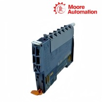
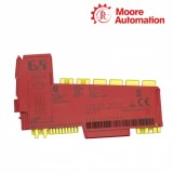
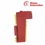
B&R X20DO2623 / X20IF10E1-1 X20 Output and Interface Modules

B&R X20DO2623 / X20IF10E1-1 X20 Output and Interface Modules Item NO.: 2942558

Write a Review
US$ 1.00
Quantity
Stock ( 28 )

Copy and share this link on social network or send it to your friends

Copy
Request Price & AvailabilitySend the part number and quantity. Our team will confirm stock, condition, lead time and the best quotation.
  • MOQ: 1 piece
  • International shipping
  • 1-year warranty on eligible items
  • Fast response during business hours
Product Name B&R X20DO2623 / X20IF10E1-1 X20 Output and Interface Modules
Item NO. 2942558
Weight 0.1 kg = 0.2205 lb = 3.5274 oz
Category B&R
Brand B&R
Creation Time 2026-11-19

B&R X20DO2623 / X20IF10E1-1 X20 Output and Interface Modules
DO / IFX20 Module

AC OUTPUT / PROFINET COMMUNICATION

B&R X20DO2623 / X20IF10E1-1 X20 Output and Interface Modules

2 + 2outputs / RJ45 ports
01

Product Introduction

B&R X20DO2623 and X20IF10E1-1 perform separate control-system duties within the B&R X20 platform. X20DO2623 is a two-channel 100 to 240 VAC SSR output module that switches field loads and regulates AC power through full-wave control, while X20IF10E1-1 is a PROFINET IO controller interface that exchanges cyclic process data, configuration and diagnostic information with decentralized PROFINET devices.

Mains power enters X20DO2623 through the L and N terminals and reaches each actuator through a source output whose solid-state relay turns on at a voltage zero crossing and turns off at a current zero crossing. Network traffic handled by X20IF10E1-1 instead passes through two shielded RJ45 ports connected by an internal switch, allowing the PROFINET line to continue to the next station without routing field voltage through the communication module.

Software gives X20DO2623 either direct digital commands or percentage values that select complete mains-wave packets, with an optional firing-pattern shift used to separate load peaks. Automation Studio configures X20IF10E1-1 with controller and device names, IP settings, process-data addresses, update and watchdog times, while the module LEDs distinguish PCI-bus state, PROFINET configuration faults and link activity on IF1 and IF2.

02

Technical Information

Specification X20DO2623 X20IF10E1-1
Brand B&R B&R
Product Name X20 AC Digital Output Module X20 PROFINET IO Controller Interface
Country Austria Austria
Primary System Role Switches and modulates AC field loads Connects the X20 controller to PROFINET IO devices
Field Interface 2 source-type SSR outputs 2 shielded RJ45 ports with integrated switch
Nominal Signal / Voltage 100 to 240 VAC, 47 to 63 Hz 100BASE-TX Ethernet
Nominal Channel / Link Rate 1 A per output; 1 A total module current 100 Mbit/s
Connection Topology 3-wire actuator connection with L and N Line or daisy-chain Ethernet topology
Switching / Duplex Behavior Zero-cross turn-on and current-zero turn-off Half- or full-duplex with autonegotiation
Control Functions Digital switching or full-wave power control PROFINET IO controller, RT process-data exchange
Internal Processing Firing-pattern table over 24 full waves netX100 controller with 8 MB SDRAM
Configuration Interface Automation Studio I/O mapping and channel mode Automation Studio DTM, GSDML and device table
Diagnostic Scope Module state and output LEDs; zero-cross status Module, network and data-transfer LEDs plus software diagnostics
Electrical Isolation Output circuit isolated from X20 bus PLC isolated from PROFINET IF1 and IF2
Maximum Segment / Supply Boundary External AC supply connected directly to module 100 m maximum between two Ethernet stations
Operating Temperature -25 to 60°C horizontal; -25 to 50°C vertical -25 to 60°C horizontal; -25 to 50°C vertical
Installation Position X20 station with 240 VAC keyed X20BM12 Interface slot in X20 PLC or expandable X20BC1083
Degree of Protection IP20 IP20
03

Separating Field Power from Network Traffic

The two modules meet at the controller but carry different forms of energy and require different commissioning boundaries.

01

AC load path

X20DO2623 receives L and N directly and places the solid-state switching element in the conductor feeding each actuator. The field circuit therefore depends on mains protection, load current and external suppression, while the X20 bus carries only the command and status data.

02

PROFINET data path

X20IF10E1-1 terminates two Ethernet segments at an internal switch. IF1 and IF2 pass frames between the controller and field devices, but neither port supplies actuator power; every connected PROFINET device keeps its own documented supply and functional earth arrangement.

03

Cabinet separation

Mains conductors for X20DO2623 and shielded Ethernet cabling for X20IF10E1-1 follow different routing and termination rules. Keeping the paths separated reduces coupling into the network and prevents a communication test from being mistaken for proof that the AC load circuit is safe or energized.

04

Coordinating Output Timing and PROFINET Cycles

A controller command reaches the field only after the output timing and network timing have each completed their own sequence.

01

Whole-wave load control

In full-wave mode, X20DO2623 converts a percentage command into complete sine-wave packets over a 24-wave pattern. Changes are accepted at the next zero crossing, so the observed heater or resistive-load response follows the mains pattern rather than the raw task-cycle edge.

02

Device update supervision

X20IF10E1-1 assigns update and watchdog times per PROFINET device. The watchdog is a multiple of the update time and reports missing cyclic data, while the separate module software watchdog supervises the application interface and must not be confused with the device watchdog.

03

Startup sequence

The X20IF10E1-1 data exchange can start automatically or under application control; the selected sequence determines when remote devices enter cyclic operation. X20DO2623 commands should be enabled only after the required communication state, output configuration and zero-cross status have been evaluated by the application.

05

Frequently Asked Questions

Which X20DO2623 setting helps prevent simultaneous load peaks without changing X20IF10E1-1 network timing?

X20DO2623 permits a full-wave firing-pattern shift to separate load peaks; use it when simultaneous AC loads disturb the supply, while X20IF10E1-1 communication should be checked through link, shielding and device diagnostics rather than by altering Ethernet timing first.

When X20DO2623 switches late after data arrives through X20IF10E1-1, which timing path should be tested first?

Separate the two timing paths: verify the update and watchdog settings on X20IF10E1-1, then verify whether X20DO2623 is using digital switching or full-wave control, because the SSR applies changes at a mains zero crossing and full-wave values follow the firing pattern.

Where can cabinet wiring interfere with both X20DO2623 control and X20IF10E1-1 diagnostics?

Incorrect cabinet routing or reference connections can couple AC switching noise from X20DO2623 into the Ethernet path of X20IF10E1-1; keep mains and shielded network conductors separated, terminate the Ethernet shield correctly and test the two circuits independently.

How should X20DO2623 and X20IF10E1-1 be checked before replacing either module?

For X20DO2623, record L/N supply, load current, channel mode and firing-pattern settings; for X20IF10E1-1, record IP data, station names, device table, process-data addresses, port settings and watchdog values before hardware is changed.

Why can X20IF10E1-1 show an active Ethernet link while an X20DO2623 load remains off?

A link LED on X20IF10E1-1 confirms that an Ethernet connection exists, not that the application has produced a valid command or that mains power reaches X20DO2623; check PROFINET device state, controller mapping, X20DO2623 L/N supply and the selected output mode.

What does an X20IF10E1-1 configuration fault mean when X20DO2623 output LEDs still operate?

The X20IF10E1-1 BF and SF indications reflect PROFINET configuration and system conditions, whereas the X20DO2623 channel LEDs reflect output commands; compare the configured device table, GSDML data and station names with the connected PROFINET devices.

06

Dedicated Account Management

Moore Automation

https://www.mvme.cn

Moore Automation assigns one account manager to keep each enquiry, clarification and delivery request within a single communication path.

Single point of contactOne account manager follows the enquiry instead of passing questions between unrelated contacts.
Technical question trackingModel, interface and accessory questions remain attached to the same customer request.
Quick turnaroundOpen items are identified early so the response can move from clarification to quotation without losing context.
Status continuityOrder and delivery updates use the same confirmed scope that was reviewed during the enquiry.

No related record found

You May Also Like

Copyright © 2004–2026 www.mvme.cn. All rights reserved.

Disclaimer: Moore Automation Limited is an independent reseller and is not an authorized distributor or representative of the manufacturers featured on this website. Product names and trademarks belong to their respective owners.