

Voltage command path
For voltage mode, the D/A converter drives the voltage amplifier and feedback network to AO+x U. The load returns through AO-x U/I, and its input impedance must be appropriate for the commanded ±10 V range.
Welcome to Moore Automation Limited

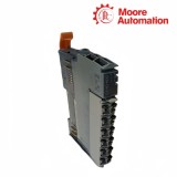

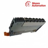

|
Copy and share this link on social network or send it to your friends
Copy| Product Name | B&R X20AO4632 X20 Analog Output Module |
| Item NO. | 2942571 |
| Weight | 0.1 kg = 0.2205 lb = 3.5274 oz |
| Category | B&R |
| Brand | B&R |
| Creation Time | 2026-11-19 |
ANALOG OUTPUT / VOLTAGE AND CURRENT
B&R X20AO4632 is a four-channel analog output module for the B&R X20 I/O system. Each channel is configured for either ±10 V or 0–20 mA and converts controller output data through a D/A stage into the selected field signal, allowing one module to drive voltage-command devices and current-loop loads on separate channels.
Terminal choice on X20AO4632 is part of the signal configuration: voltage loads use AO+x U and AO-x U/I, while current loads use AO+x I and AO-x U/I. An internal enable relay controls startup, the output stage is short-circuit proof, and the channel status path reports the output condition without replacing a field measurement at the connected device.
The X20AO4632 software model supports direct output values and time-controlled values with latch and delay settings. When coordinated changes are required, the controller writes the channel data and timing parameters as one designed sequence; changing a terminal from voltage to current without matching the channel type and scaling can drive the load with the wrong physical quantity.
| Brand | B&R |
|---|---|
| Model | X20AO4632 |
| Product Name | X20 Analog Output Module |
| Country | Austria |
| Output Quantity | 4 |
| Signal Ranges | ±10 V or 0–20 mA |
| Output Selection | Per channel through configuration and terminal path |
| Converter Resolution | 16 bit |
| Voltage Terminals | AO+x U and AO-x U/I |
| Current Terminals | AO+x I and AO-x U/I |
| Startup Behavior | Internal enable relay |
| Output Protection | Short-circuit proof |
| Output Filter | First-order low-pass, 10 kHz cutoff |
| Timed Output Data | Delayed values with latch / delay configuration |
| Isolation | Output group isolated from bus |
| Operating Temperature | -25 to 60°C horizontal; -25 to 50°C vertical |
| Required Station Parts | X20BM11 and X20TB12 |
| Degree of Protection | IP20 |
One software channel can use two different electrical stages, selected by configuration and wiring.
For voltage mode, the D/A converter drives the voltage amplifier and feedback network to AO+x U. The load returns through AO-x U/I, and its input impedance must be appropriate for the commanded ±10 V range.
For current mode, the stage controls loop current through AO+x I and the shared return terminal. Loop continuity and load resistance determine whether the commanded current can be established across the connected device.
Terminal placement, channel type and application scaling must all describe the same mode. If one element remains in the previous configuration, the online numeric command can look correct while the physical output is wrong or limited.
The module can apply output data immediately or through configured timing registers.
Normal analog output data follows the controller update path and is filtered by the output stage. This mode suits independently changing setpoints when no cross-channel timing relationship is required.
Delayed registers hold alternate channel data and the delay configuration decides when they replace or accompany the direct values. The application must update the intended value set before arming the timing action.
Latch timing provides a defined point for applying coordinated changes. Controller task timing, bus cycle and module configuration should be validated together when several analog commands must change in a controlled sequence.
For X20AO4632, move the conductor to AO+x I, retain AO-x U/I as the return, configure the channel for current and verify loop continuity and load resistance.
Review the X20AO4632 channel type, controller initialization data, enable behavior and any delayed or latched output registers before changing field wiring.
For X20AO4632, document direct values, delayed values, delay mask and latch timing, then test the sequence with the field device in a safe state and confirm the physical output.
An X20AO4632 status indication confirms module-side operation, but it does not prove the field device received the command; measure voltage or loop current at the connected device to verify the complete path.
Check the X20AO4632 voltage terminal path, load input impedance, conductor return and channel configuration; a current-mode connection or excessive load can prevent the expected voltage.
Use the exact X20AO4632 documentation and hardware configuration for X20AO4632; X20AO4632-1 is a separate order number and its data should not be substituted without a verified migration review.
Moore Automation links packing, destination and tracking details to the confirmed model list.


Moore Automation Sales Team
Copyright © 2004–2026 www.mvme.cn. All rights reserved.
Disclaimer: Moore Automation Limited is an independent reseller and is not an authorized distributor or representative of the manufacturers featured on this website. Product names and trademarks belong to their respective owners.
No related record found