

Assign channel direction
Define each channel as input or output before loop checkout. Direction is a software attribute, so an incorrect database assignment can contradict the actual field wiring.
Welcome to Moore Automation Limited



|
Copy and share this link on social network or send it to your friends
Copy| Product Name | Yokogawa A2MDV843-0S1000 16-Channel Isolated Digital I/O Module |
| Item NO. | 2932297 |
| Weight | 0.1 kg = 0.2205 lb = 3.5274 oz |
| Category | YOKOGAWA |
| Brand | YOKOGAWA |
| Creation Time | 2026-11-13 |
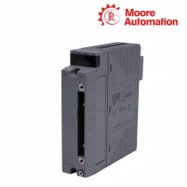
Yokogawa A2MDV843-0S1000 is a 16-channel isolated digital I/O module for the N-IO platform. Each channel can be assigned in software as a digital input or digital output, giving the same hardware a defined mixture of sensing and actuation points within one node.
The 0S1000 suffix of A2MDV843-0S1000 identifies the fixed leading code, the standard digital I/O type, the fixed design code, non-explosion construction and basic environmental treatment. The module accepts dry-contact input arrangements and provides transistor output capability for 24 V DC field circuits.
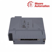
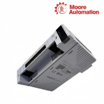
Channel isolation in A2MDV843-0S1000 separates every field point from the system and from the other channels. Its slim N-IO body and front connector projection define the space occupied by the module, base connection and field-wiring interface inside the enclosure.

| Specification | A2MDV843-0S1000 |
|---|---|
| Brand | Yokogawa |
| Product Name | 16-Channel Isolated Digital I/O Module |
| Country | Not specified |
| Platform | N-IO |
| Channel count | 16 |
| Channel assignment | Digital input or digital output selectable by software |
| Input type | Dry contact input |
| Output type | Transistor contact output |
| Nominal field supply | 24 V DC |
| Maximum output current | 700 mA per channel at 24 V DC |
| Isolation | Channel-to-system and channel-to-channel |
| Withstanding voltage | 1500 V AC |
| Explosion protection | Not included |
| Environmental class | Basic |
| Approximate weight | 0.41 kg |
A2MDV843-0S1000 becomes a usable I/O set only after every physical channel has a declared direction, signal behavior and engineering identity.
Define each channel as input or output before loop checkout. Direction is a software attribute, so an incorrect database assignment can contradict the actual field wiring.
For inputs, define normal and abnormal contact states. For outputs, document the commanded safe state and the load supplied by the 24 V DC circuit.
Assign every A2MDV843-0S1000 channel a unique point name and terminal reference so the downloaded channel direction, displayed state and cabinet connection describe the same physical point.
Diagnostics for A2MDV843-0S1000 should separate module health, channel direction, field supply and load behavior instead of treating every missing state as an I/O hardware failure.
Measure the 24 V DC field source at the terminal interface under load. A healthy module cannot drive an output whose external supply or return path is absent.
For an output fault, compare the application command, configured channel direction and measured terminal state. For an input fault, compare contact continuity with the received state.
Keep output current within the documented 700 mA limit and apply the external circuit protection required by the field device and cabinet design.
A2MDV843-0S1000 has a documented current limit, but the load type, inrush, suppression, external protection and shared supply capacity still require review. A steady-state current below 700 mA does not prove the transient is acceptable.
Compare the A2MDV843-0S1000 engineering assignment with the cabinet wiring list for all 16 channels. A channel wired as a contact input but configured as an output will not be corrected by field-device replacement.
A simultaneous drop on several A2MDV843-0S1000 outputs points first to shared 24 V DC capacity, return wiring, protection or load inrush rather than several independent channel failures.
A2MDV843-0S1000 isolates channels from one another, so a fault limited to one point often indicates its field loop, supply or configuration. A pattern across several points suggests a shared external source or node-level condition.
For A2MDV843-0S1000, confirm that the channel is configured as an output, that the 24 V DC field supply and return are present, and that the load is within the channel rating before replacing the module.
Before moving A2MDV843-0S1000, export or document the channel-direction map, tags, safe states, node position and terminal mapping. The hardware alone does not preserve the application meaning of each point.
Moore Automation customer support begins by checking the manufacturer, complete model, quantity, destination and any available label image. This gives quotation and documentation discussions one consistent reference.
The team can then coordinate document requests, packing questions, shipment status and tracking information without mixing the requested item with a similar family code.

Moore Automation Sales Team
Copyright © 2004–2026 www.mvme.cn. All rights reserved.
Disclaimer: Moore Automation Limited is an independent reseller and is not an authorized distributor or representative of the manufacturers featured on this website. Product names and trademarks belong to their respective owners.


No related record found