Install Siemens 6ES7288-5AE01-0AA0 as a controlled sequence: isolate the controller, seat the board, complete the analog loop, then configure and verify the selected input mode. This order prevents a mechanical installation from being mistaken for a commissioned measurement channel.
01
1. Seat the signal board
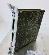
Remove power from the supported CPU before handling Siemens 6ES7288-5AE01-0AA0. Open the signal-board position, align the board with the internal connector, press it fully into place without forcing the terminals, and close the cover only after the board sits level and secure.
02
2. Route the analog circuit
Wire Siemens 6ES7288-5AE01-0AA0 for the intended voltage or current mode using the exact signal and reference terminals. Keep the analog cable away from contactor, motor and variable-frequency-drive conductors; terminate the shield according to the cabinet grounding plan rather than using it as the measurement return.
03
3. Configure and prove the loop
Add Siemens 6ES7288-5AE01-0AA0 to the CPU hardware configuration, select the same electrical range used by the transmitter and download the project. Before service, compare a known field value with the board terminals, raw PLC value and scaled engineering value so wiring, conversion and program scaling are proven separately.









No related record found