


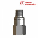
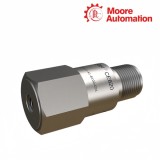
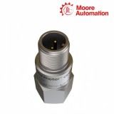
Welcome to Moore Automation Limited

0
Loadding...
 

sales@mvme.cn    Phone: +86 18030175807

Home>VIBRO METER>Meggitt Vibro-Meter CE620 444-620-000-111-A1-B100-C01 | CE620 100 mV/g piezoelectric accelerometer
Meggitt Vibro-Meter CE620 444-620-000-111-A1-B100-C01 | CE620 100 mV/g piezoelectric accelerometer

Meggitt Vibro-Meter CE620 444-620-000-111-A1-B100-C01 | CE620 100 mV/g piezoelectric accelerometer Item NO.: 2921994

Write a Review
US$ 1.00
Quantity
Stock ( 28 )

Copy and share this link on social network or send it to your friends

Copy
Request Price & AvailabilitySend the part number and quantity. Our team will confirm stock, condition, lead time and the best quotation.
  • MOQ: 1 piece
  • International shipping
  • 1-year warranty on eligible items
  • Fast response during business hours
Product Name Meggitt Vibro-Meter CE620 444-620-000-111-A1-B100-C01 | CE620 100 mV/g piezoelectric accelerometer
Item NO. 2921994
Weight 0.1 kg = 0.2205 lb = 3.5274 oz
Category VIBRO METER
Brand OTHER PRODUCTS
Creation Time 2026-10-16

Meggitt Vibro-Meter CE620 444-620-000-111-A1-B100-C01 | CE620 100 mV/g piezoelectric accelerometer
Meggitt Vibro-Meter · CE620 accelerometers with integrated electronics

Meggitt Vibro-Meter CE620 444-620-000-111-A1-B100-C01 | CE620 100 mV/g piezoelectric accelerometer

Converts machine acceleration into a low-impedance voltage signal for monitoring electronics

01

Product Description

Meggitt Vibro-Meter CE620 444-620-000-111-A1-B100-C01 is the standard, non-Ex, sensor-only CE620 accelerometer with integrated electronics and 100 mV/g sensitivity. It converts machine acceleration into a low-impedance voltage signal for the connected monitoring input.

A constant-current source supplies CE620 444-620-000-111-A1-B100-C01 through the same two-wire path used by the measurement signal. The internal electronics bias the output and buffer the piezoelectric element so the receiving channel sees a voltage proportional to acceleration.

The case of CE620 444-620-000-111-A1-B100-C01 is isolated from the internal shield. Reverse-polarity and overvoltage protection act at the electrical input, while mechanical mounting through the selected adaptor stud establishes the vibration path from the machine surface.

CE620 sensor-only mechanical and ordering drawing
Full-size CE620 sensor-only mechanical and ordering drawing×
02

Product Specifications

Brand
Meggitt Vibro-Meter
Product type
CE620 accelerometer with integrated electronics
Product family
CE620
Complete model
CE620 444-620-000-111-A1-B100-C01
Version
Standard non-Ex, sensor only
Sensitivity code
B100
Sensitivity
100 mV/g ±5%
Dynamic range
±80 g peak
Transverse sensitivity
Less than 5%
Linearity
±1% maximum
Frequency response ±10%
1 to 9000 Hz
Frequency response ±3 dB
0.5 to 14000 Hz
Resonant frequency
25 kHz nominal
Supply voltage
22 to 28 VDC
Supply current
2 to 10 mA
Bias voltage at 4 mA
12 VDC nominal
Output impedance
50 ohm nominal
Case isolation
100 Mohm minimum
Grounding
Isolated from case and internally shielded
Electrical protection
Reverse-polarity and overvoltage protected
Supplied adaptor studs
1/4-28UNF and M8 × 1.25
03

Performance Characteristics

The B100 configuration of CE620 444-620-000-111-A1-B100-C01 fixes a 100 mV/g voltage scale, an ±80 g peak range and the frequency response used by the receiving IEPE channel.

  1. 01

    Sensitivity and dynamic range

    CE620 444-620-000-111-A1-B100-C01 changes its output by a nominal 100 mV for each g of acceleration. At that scale the specified dynamic range is ±80 g peak around the bias level.

  2. 02

    Frequency response

    CE620 444-620-000-111-A1-B100-C01 remains within ±10% from 1 to 9000 Hz and within ±3 dB from 0.5 to 14000 Hz. The nominal 25 kHz resonance stays outside those normal measurement bands.

  3. 03

    Bias and output impedance

    A 4 mA constant-current supply establishes a nominal 12 VDC bias in CE620 444-620-000-111-A1-B100-C01. Dynamic acceleration appears as an AC voltage around that bias through a nominal 50 ohm output.

04

Installation Highlights

The sensor-only C01 version separates the mechanical adaptor, external cable and constant-current input, so each interface is installed without changing the CE620 measurement scale.

  1. 01

    Adaptor and mounting torque

    CE620 444-620-000-111-A1-B100-C01 is supplied with 1/4-28UNF and M8 × 1.25 adaptor studs. The selected stud is tightened to the specified 2.4 N·m mounting torque against the prepared machine surface.

  2. 02

    Connector pin relationship

    The MIL-C-5015 connector on CE620 444-620-000-111-A1-B100-C01 uses pin A for signal/power and pin B for common. The external two-wire cable therefore carries both constant-current excitation and the conditioned voltage.

  3. 03

    Case-isolated signal path

    The internal shield of CE620 444-620-000-111-A1-B100-C01 remains isolated from the machine case. Reverse-polarity and overvoltage protection act at the electrical input before the signal reaches the monitoring channel.

05

Common Questions

What do the A1, B100 and C01 fields define in CE620 444-620-000-111-A1-B100-C01?

A1 identifies the standard non-Ex version, B100 selects 100 mV/g sensitivity, and C01 is the sensor-only connection option for CE620 444-620-000-111-A1-B100-C01.

Which power source is required by CE620 444-620-000-111-A1-B100-C01?

Use a 22 to 28 VDC constant-current source delivering 2 to 10 mA to CE620 444-620-000-111-A1-B100-C01 through its two-wire measurement path.

How should a monitoring input interpret CE620 444-620-000-111-A1-B100-C01 sensitivity?

For CE620 444-620-000-111-A1-B100-C01, 1 g of acceleration corresponds to a nominal 100 mV change around the sensor bias level.

Which mounting studs are supplied with CE620 444-620-000-111-A1-B100-C01?

CE620 444-620-000-111-A1-B100-C01 is supplied with 1/4-28UNF and M8 × 1.25 adaptor studs; the selected stud must match the prepared mounting interface.

Why does case isolation matter for CE620 444-620-000-111-A1-B100-C01?

Internal isolation keeps the signal shield of CE620 444-620-000-111-A1-B100-C01 separate from the machine case, helping prevent an unintended case-current path.

What should be checked if CE620 444-620-000-111-A1-B100-C01 stays near its bias voltage?

A steady bias near 12 V indicates that power reaches CE620 444-620-000-111-A1-B100-C01; then check mounting motion, cable continuity and the monitoring input’s AC signal measurement.

06

Our Advantages

Moore Automation

Moore Automation combines a multi-brand industrial automation product scope with structured model records. Technical identity, quantity, destination and order progress stay aligned under the same complete product reference.

Nameplate photographs, existing drawings and installed-system details can be kept with the complete requested identifier. This gives technical, commercial and logistics records one consistent product reference.

One product recordTechnical and commercial details stay together
Industrial scopeAutomation and machinery-monitoring hardware
Document continuityModels, drawings and shipment records stay linked
Moore Automation our advantages imagewww.mvme.cn
Full-size Moore Automation image×
08

Enquiry Information

Enquiry Information

Discuss the exact product reference and installed-system requirement with Moore Automation.

ManagerLeonia
Emailsales@mvme.cnWhatsApp+86 180 3017 5807
Moore Automation · CE620 100 mV/g piezoelectric accelerometerModel reference: CE620 444-620-000-111-A1-B100-C01

No related record found

Copyright © 2004–2026 www.mvme.cn. All rights reserved.

Disclaimer: Moore Automation Limited is an independent reseller and is not an authorized distributor or representative of the manufacturers featured on this website. Product names and trademarks belong to their respective owners.