





Product Overview
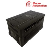
GE VersaMax Micro IC200UDR006 and IC200UDR010 are 28-point controllers for relay-output machine control. IC200UDR006 uses 12 VDC power, 16 × 12 VDC inputs, and 12 relay outputs. IC200UDR010 uses 24 VDC power, 16 × 24 VDC inputs, 11 relay outputs, and one DC output. Both use normally-open relay circuits for varied field loads, but their power and input standards are different and must be checked before replacement.
Technical Data
| Technical item | IC200UDR006 | IC200UDR010 |
|---|---|---|
| Brand | GE | |
| Product type | VersaMax Micro PLC controller with relay and DC outputs | |
| Built-in I/O | 28 points | |
| Discrete inputs | 16 × 12 VDC | 16 × 24 VDC |
| Outputs | 12 × normally-open relay, 2 A | 11 × normally-open relay, 2 A; 1 × DC output |
| Controller power | 12 VDC nominal | 24 VDC nominal |
| Input range | 0–15 VDC | 0–30 VDC |
| High-speed counter frequency | 10 kHz | |
| Pulse / PWM capability | Not available on relays | Q1 supports up to 5 kHz |
Product Features
Both models accept sixteen configurable DC inputs and support 10 kHz high-speed counting. The practical control difference is the output allocation: one model has twelve relay points, while the other adds a dedicated DC Q1 output alongside eleven relays.
Use the point map to identify whether a commanded function belongs on a relay output or the dedicated Q1 DC point. This keeps the controller's 10 kHz input function and its output allocation separate during troubleshooting.
Wiring Reference
Use the correct official wiring diagram for the exact model during panel work. The diagrams below are cropped from the manufacturer user manual to retain terminal labels while removing manual headers and margins. Select the supply, field wiring, and output circuit for the actual model—not a neighbouring family member.


Output Protection
Use the dedicated Q1 DC circuit only where the documented application needs it, with its external fuse and correct DC load. Relay points are for switching loads within their contact ratings; they do not provide a substitute for pulse/PWM output functions.
A Q1 symptom should first be checked at its external fuse, DC supply and field load. Relay-output symptoms should instead be compared with the recorded contact load and terminal assignment, because the protection path is different.
Product FAQ
What distinguishes IC200UDR006 / IC200UDR010 output allocations?
One has twelve relays; the other has eleven relays plus a dedicated Q1 DC output.
Why does IC200UDR006 / IC200UDR010 Q1 need external fusing?
A shorted DC load can damage that circuit, so retain the documented fuse.
How should IC200UDR006 / IC200UDR010 high-speed inputs be preserved?
Record which of the sixteen inputs is configured for 10 kHz counting before replacement.
Can IC200UDR006 / IC200UDR010 relay points create pulse output?
No; use the intended DC output/function rather than treating a relay as PWM hardware.
What supply mismatch can prevent IC200UDR006 / IC200UDR010 startup?
A 12 VDC versus 24 VDC controller/input mismatch.
Where should an IC200UDR006 / IC200UDR010 output fault be checked first?
At the individual load circuit, including the Q1 fuse where that DC point is involved.
Moore Automation
Moore Automation supplies industrial automation parts for maintenance and replacement planning, including PLC, DCS, HMI, drives, and related components.
- Original products
- Fast delivery
- 1-year warranty
- 12-hour online response



No related record found