HCS01.1E-W0013-A-02-B-ET-EC-NN-L3-NN-FW and HCS01.1E-W0018-A-03-B-ET-EC-NN-L3-NN-FW are Bosch Rexroth IndraDrive Cs HCS01 compact single-axis converters with the same Basic control-section, ET Multi-Ethernet, EC encoder and L3 option structure. Their primary difference begins in the power section: W0013 uses the -02 110–230 V class, while W0018 uses the -03 200–500 V three-phase class.
Through X22 and X23, HCS01.1E-W0013-A-02-B-ET-EC-NN-L3-NN-FW and HCS01.1E-W0018-A-03-B-ET-EC-NN-L3-NN-FW exchange network commands over ET, and X4 receives EC motor-encoder feedback. The control section combines these data paths with firmware-assigned digital I/O and presents the Bb ready contact at X47; this shared signal architecture does not remove the different mains and motor-output boundaries.
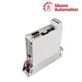
Mechanically, HCS01.1E-W0013-A-02-B-ET-EC-NN-L3-NN-FW and HCS01.1E-W0018-A-03-B-ET-EC-NN-L3-NN-FW also occupy different frames. W0013 is 50 mm wide and 215 mm high, whereas W0018 is 70 mm wide and 268 mm high; the -03 W0018 additionally exposes the X77 DC-bus connection that is not available on the -02 W0013 device.
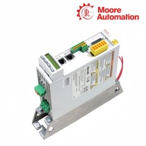
HCS01 connection-point families for power, encoder, Ethernet, I/O and relay wiring.
02
Product Data
Attribute
HCS01.1E-W0013-A-02-B-ET-EC-NN-L3-NN-FW
HCS01.1E-W0018-A-03-B-ET-EC-NN-L3-NN-FW
Brand
Bosch Rexroth
Bosch Rexroth
Product type
Compact single-axis converter
Compact single-axis converter
Rated power input
1 or 3 × AC 110…230 V
3 × AC 200…500 V
Rated input current
8.3 A / 4.5 A
5.0 A
Output voltage
3 × AC 0…230 V
3 × AC 0…500 V
Output current
4.5 A
7.6 A
Control-voltage input
24 V ±20%
24 V ±20%
Mass
1.30 kg
2.10 kg
Housing height
215 mm
268 mm
Housing width
50 mm
70 mm
Housing depth
196 mm
196 mm
DC-bus connection X77
Not available
Available
ET / EC interfaces
X22/X23 / X4
X22/X23 / X4
03
Two voltage classes under one control architecture
The communication and feedback connectors match, while the mains, DC-bus and motor-output circuits follow different voltage classes.
01
W0013 -02 power path
The W0013 member of HCS01.1E-W0013-A-02-B-ET-EC-NN-L3-NN-FW and HCS01.1E-W0018-A-03-B-ET-EC-NN-L3-NN-FW routes its -02 mains class through the internal rectifier and DC link before the inverter forms the motor phases. Its connection boundary ends without an external X77 DC-bus terminal.
02
W0018 -03 power path
The W0018 member of HCS01.1E-W0013-A-02-B-ET-EC-NN-L3-NN-FW and HCS01.1E-W0018-A-03-B-ET-EC-NN-L3-NN-FW uses the -03 three-phase power path and exposes the internal bus at X77 as L+ and L-. X77 extends DC-bus access; it is not an additional motor or mains output.
03
Shared Basic control section
Both members of HCS01.1E-W0013-A-02-B-ET-EC-NN-L3-NN-FW and HCS01.1E-W0018-A-03-B-ET-EC-NN-L3-NN-FW route ET traffic through X22/X23 and encoder data through X4. The shared control design processes those signals within different power-stage envelopes.
04
Connection points reveal the boundary change
Connector presence and conductor role provide a direct way to distinguish the two power frames after the control options are confirmed.
Power connector families
X3 and X5 carry mains and motor power on both members of HCS01.1E-W0013-A-02-B-ET-EC-NN-L3-NN-FW and HCS01.1E-W0018-A-03-B-ET-EC-NN-L3-NN-FW, but their voltage and current values follow the -02 and -03 tables rather than one shared rating.
DC-bus access
Only the W0018 -03 member of HCS01.1E-W0013-A-02-B-ET-EC-NN-L3-NN-FW and HCS01.1E-W0018-A-03-B-ET-EC-NN-L3-NN-FW provides X77 for L+ and L-. The absence of X77 on W0013 is a design difference, not a missing accessory.
Housing and conductor space
The narrower W0013 and wider W0018 frames in HCS01.1E-W0013-A-02-B-ET-EC-NN-L3-NN-FW and HCS01.1E-W0018-A-03-B-ET-EC-NN-L3-NN-FW require different front-panel and termination space. Even where housing depth is shared, conductor entry and mounting-hole position must follow the drawing for the actual power frame.
1. For HCS01.1E-W0013-A-02-B-ET-EC-NN-L3-NN-FW and HCS01.1E-W0018-A-03-B-ET-EC-NN-L3-NN-FW, can the two converters use the same mains voltage?
No. W0013 belongs to the -02 110–230 V class, while W0018 belongs to the -03 200–500 V three-phase class on HCS01.1E-W0013-A-02-B-ET-EC-NN-L3-NN-FW and HCS01.1E-W0018-A-03-B-ET-EC-NN-L3-NN-FW.
2. Why do both codes still contain ET and EC on HCS01.1E-W0013-A-02-B-ET-EC-NN-L3-NN-FW and HCS01.1E-W0018-A-03-B-ET-EC-NN-L3-NN-FW?
For HCS01.1E-W0013-A-02-B-ET-EC-NN-L3-NN-FW and HCS01.1E-W0018-A-03-B-ET-EC-NN-L3-NN-FW, their control sections share Multi-Ethernet at X22/X23 and motor-encoder feedback at X4 even though their power sections differ.
3. HCS01.1E-W0013-A-02-B-ET-EC-NN-L3-NN-FW and HCS01.1E-W0018-A-03-B-ET-EC-NN-L3-NN-FW: Which model provides the X77 DC-bus terminals?
With HCS01.1E-W0013-A-02-B-ET-EC-NN-L3-NN-FW and HCS01.1E-W0018-A-03-B-ET-EC-NN-L3-NN-FW, the W0018 -03 device provides X77; the W0013 -02 device does not.
4. How do their motor-output voltage ranges differ for HCS01.1E-W0013-A-02-B-ET-EC-NN-L3-NN-FW and HCS01.1E-W0018-A-03-B-ET-EC-NN-L3-NN-FW?
W0013 produces 3 × AC 0–230 V, while W0018 produces 3 × AC 0–500 V for HCS01.1E-W0013-A-02-B-ET-EC-NN-L3-NN-FW and HCS01.1E-W0018-A-03-B-ET-EC-NN-L3-NN-FW.
5. Regarding HCS01.1E-W0013-A-02-B-ET-EC-NN-L3-NN-FW and HCS01.1E-W0018-A-03-B-ET-EC-NN-L3-NN-FW, do they occupy the same front-panel area?
On HCS01.1E-W0013-A-02-B-ET-EC-NN-L3-NN-FW and HCS01.1E-W0018-A-03-B-ET-EC-NN-L3-NN-FW, no. W0013 is 50 mm wide × 215 mm high; W0018 is 70 mm wide × 268 mm high.
6. Which code positions must remain visible in a paired enquiry with HCS01.1E-W0013-A-02-B-ET-EC-NN-L3-NN-FW and HCS01.1E-W0018-A-03-B-ET-EC-NN-L3-NN-FW?
In HCS01.1E-W0013-A-02-B-ET-EC-NN-L3-NN-FW and HCS01.1E-W0018-A-03-B-ET-EC-NN-L3-NN-FW, keep each full model, including W current class, -02/-03 voltage class, B, ET, EC, L3 and FW, so the shared options do not hide the power difference.
Moore Automation enters the two complete HCS01 codes on separate evidence rows. The shared ET, EC and L3 fields are repeated intentionally, while voltage class, output range, frame size and X77 presence remain model-specific.
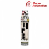
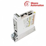
A front and lower-connector photograph for each device can show both the label and terminal layout. This makes the -03 DC-bus connection visible without using it as a substitute for the type plate.
-02 and -03 never mergedShared options repeated explicitlyX77 presence captured visuallyFrame dimensions tied to each code
Disclaimer: Moore Automation Limited is an independent reseller and is not an authorized distributor or representative of the manufacturers featured on this website. Product names and trademarks belong to their respective owners.





No related record found