

X60 conductor roles
Pins 2 and 4 carry the CAN differential pair. Pin 3 terminates the shield, while pins 1 and 5 form the V−/V+ interface-supply pair. Keeping these roles separate prevents the bus supply from being confused with a signal conductor.
Welcome to Moore Automation Limited


|
Copy and share this link on social network or send it to your friends
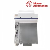
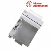
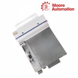
Copy| Product Name | Bosch Rexroth DKC06.3-040-7-FW ECODRIVE03 DeviceNet Drive Controller |
| Item NO. | 2943171 |
| Weight | 0.1 kg = 0.2205 lb = 3.5274 oz |
| Category | BOSCH |
| Brand | BOSCH |
| Creation Time | 2026-11-19 |
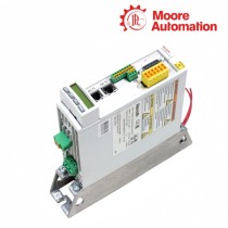
Bosch Rexroth DKC06.3-040-7-FW is an ECODRIVE03 drive controller whose DKC06.3 command-communication variant uses DeviceNet. Within the drive system, DKC06.3-040-7-FW receives network commands through the command interface, converts the incoming mains supply into a controlled motor output, and returns controller status through the drive and communication diagnostics.
At X60, DKC06.3-040-7-FW separates the DeviceNet connection into V−, CAN−, shield, CAN+ and V+ across five pins. CAN− and CAN+ form the differential signal pair, the shield has its own connection point, and V−/V+ carry the interface supply. The six H60–H65 indicators are grouped beside X60 so the communication-state display remains physically associated with the bus connector.
Inside DKC06.3-040-7-FW, the line input passes through a bridge rectifier and charging-current limit before reaching the DC-bus capacitance; the converter bridge then produces the three-phase A1/A2/A3 motor output. The separate X1 control-voltage input accepts 19.2…28.8 V DC and supplies the controller electronics, while the 20 W base figure excludes external loads connected to the control outputs and encoder interface.

| Attribute | DKC06.3-040-7-FW |
|---|---|
| Brand | Bosch Rexroth Indramat |
| Product Name | ECODRIVE03 DeviceNet drive controller |
| Country | Germany |
| Command communication | DeviceNet interface |
| DeviceNet connector | X60, male, 5 pins |
| Mains input | 1 × AC or 3 × AC 200…480 V ±10% |
| Mains frequency | 50…60 Hz ±2 Hz |
| Switching frequency | 4 kHz or 8 kHz, selectable |
| Type current / peak current 1 | 40 A |
| Continuous current 2 at 4 kHz | 16 A |
| Continuous current 2 at 8 kHz | 12.5 A |
| DC-bus voltage | 300…800 V DC, dependent on mains input |
| Control voltage at X1 | 19.2…28.8 V DC |
| Control-power consumption | 20 W without external control-output or encoder-interface load |
| Mass / protection | 5.7 kg / IP20 |
The communication boundary on DKC06.3-040-7-FW can be read from the physical connector inward: the bus cable lands at X60, its conductors retain separate signal, shield and supply roles, and the adjacent indicator group presents interface status.
Pins 2 and 4 carry the CAN differential pair. Pin 3 terminates the shield, while pins 1 and 5 form the V−/V+ interface-supply pair. Keeping these roles separate prevents the bus supply from being confused with a signal conductor.
The DeviceNet connector permits a maximum bus voltage of +30 V. The current drawn through the connector changes with bus voltage, so the bus-power calculation belongs to the communication network and remains separate from the X1 controller supply.
DeviceNet participant connections use the specified open screw connector and network cabling, with a 121 Ω, 1%, ¼ W termination at the bus end. H60–H65 form the local diagnostic display; their state definitions follow the installed firmware function set.
The 040 power stage explains how the mains, DC bus and motor output are linked, while the current and environmental limits define how much of that conversion path can be used continuously.
Single- or three-phase 200…480 V AC enters the bridge rectifier. The charging-current limiter controls the initial charge of the 0.27 mF nominal DC-bus capacitance, and the bleeder circuit is connected across the same L+/L− rails.
The converter bridge switches the DC-bus energy to A1, A2 and A3. At 4 kHz the continuous-current-2 value is 16 A; selecting 8 kHz changes that continuous value to 12.5 A, even though the type-current value remains 40 A.
The power section and bleeder use an internal blower. Full published output ratings apply with +5…+45 °C inlet air and installation altitude up to 1000 m; the IP20 controller therefore depends on a control cabinet that maintains airflow and environmental limits.
For DKC06.3-040-7-FW, check that the complete type code contains DKC06.3 and identify the five-pin male X60 connector beside the H60–H65 diagnostic display. This physical arrangement distinguishes the DeviceNet command interface from other ECODRIVE03 communication variants.
On DKC06.3-040-7-FW, X60 pin 1 is V−, pin 2 is CAN−, pin 3 is the shield connection, pin 4 is CAN+, and pin 5 is V+. Keeping the differential pair on CAN− and CAN+ while landing the shield on its assigned pin preserves the interface boundary shown for DKC06.3.
No. The V+ and V− conductors at X60 supply the DeviceNet interface of DKC06.3-040-7-FW; they do not replace the mains input or the separate 19.2…28.8 V DC control-voltage connection at X1. The DeviceNet bus voltage is limited to +30 V.
The 40 A figure for DKC06.3-040-7-FW is the type current and first peak-current value, not a continuous rating. The continuous-current-2 value is 16 A at a 4 kHz switching frequency and 12.5 A at 8 kHz, so the active switching-frequency setting must be considered with the motor data.
The base control-power consumption of DKC06.3-040-7-FW is 20 W at X1 without external loads on the control outputs or encoder interface. Add those external loads separately, keep the supply inside 19.2…28.8 V DC, and account for the control-voltage charging current when several controllers are energized together.
The published output ratings for DKC06.3-040-7-FW apply from +5 to +45 °C and up to 1000 m installation altitude. Because the controller is IP20 and uses an internal blower for the power section, the cabinet must maintain the air-inlet temperature and keep contamination and condensation within the stated operating limits.

Moore Automation supports industrial automation enquiries with one account contact coordinating model review, quotation information and shipment updates. Exact product codes, type-plate details and requested quantities keep the enquiry record clear before commercial information is prepared.
For international deliveries, available carrier and tracking details are coordinated with secure packaging and dispatch information. The supply scope covers automation components from established manufacturers, including enquiries for rare and obsolete parts.

Moore Automation Sales Team
Copyright © 2004–2026 www.mvme.cn. All rights reserved.
Disclaimer: Moore Automation Limited is an independent reseller and is not an authorized distributor or representative of the manufacturers featured on this website. Product names and trademarks belong to their respective owners.
No related record found