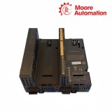
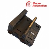
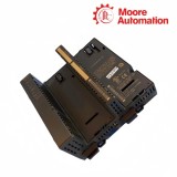
GE IC694ALG390C RX3i 2-Channel Analog Voltage Output Module
GEPACSystems RX3i
Analog Output
Two-channel voltage output
GE IC694ALG390C RX3i 2-Channel Analog Voltage Output Module
Bipolar field output with scan-synchronous channel updates
Product facts
Product Description
GE IC694ALG390C is a two-channel PACSystems RX3i analog voltage output module. Each channel converts signed controller data into a field signal from -10 to +10 V. The conversion path uses twelve magnitude bits plus a sign bit, giving an effective 13-bit bipolar representation for commanded output values.
GE IC694ALG390C receives each channel command through the PLC analog-output table and refreshes both outputs on every controller scan. A command of zero maps to 0 V, while the positive and negative limits of the signed scaling map to the corresponding ends of the voltage range. This keeps software scaling and terminal voltage on the same bipolar center point.
GE IC694ALG390C separates channel output, common, shield and isolated power connections on its removable terminal block. The output-default jumper selects either 0 V or the last commanded value during CPU Stop or Reset, and an external isolated 24 V source can maintain the output circuitry when the backplane source is unavailable. Dedicated channel commons keep the two load circuits distinct, while separate shield points provide defined landing positions for the cable screens.
Reference values
Technical Data
Brand
GE
Model
IC694ALG390C
Product Name
RX3i 2-Channel Analog Voltage Output Module
Country
Not specified
Output Channels
2
Output Range
-10 to +10 V
Digital Conversion
12-bit magnitude plus sign (effective 13 bits)
Resolution
2.5 mV per count
Update Rate
Approximately 5 ms for both channels; application-dependent
Absolute Accuracy
±5 mV at 25 °C
Output Load
5 mA maximum; 2 kΩ minimum resistance
Load Capacitance
2000 pF maximum
Supply Sources
+5 V DC backplane and isolated +24 V DC
External Supply
18 to 30 V DC; 10% maximum ripple
Isolation
250 V AC continuous; 1500 V DC for one minute
Signal behavior
Operating Characteristics
The two output paths share a bipolar numeric center, a scan-based refresh sequence and defined electrical loading limits. Together these details explain how a controller command becomes a stable field voltage.
Command path
Signed data becomes bipolar voltage
IC694ALG390C reads a 16-bit two’s-complement value from each analog-output word. The significant bits are converted to sign-and-magnitude form: zero produces 0 V, while the positive and negative endpoints map to the corresponding ends of the ±10 V span.
Channel timing
Both channels follow the controller scan
IC694ALG390C refreshes both channel outputs on every PLC scan. The conversion of both channels takes approximately 5 ms, although the complete response also depends on application execution and scan timing.
External circuit
The connected load shapes settling
IC694ALG390C is intended for a minimum 2 kΩ resistive load, no more than 5 mA per channel and up to 2000 pF of load capacitance. Keeping the field circuit inside these boundaries preserves the specified voltage behavior and response.
Terminal planning
Installation Highlights
Installation is organized around three independent checks: channel wiring, the output-default jumper and the isolated 24 V source. The checks keep normal output behavior and controller-stop behavior unambiguous.
Field wiring
Keep each channel with its own common
On IC694ALG390C, Output 1 uses terminals 3 and 5, while Output 2 uses terminals 4 and 6. Cable shields terminate at points 7 and 8. Twisted shielded instrumentation cable keeps signal, common and shield routing together at the module boundary.
Stop state
Set the output-default jumper deliberately
For IC694ALG390C, a jumper across terminals 11 and 13 selects 0 V when the CPU enters Stop or Reset. Removing the jumper selects Hold Last State, so the existing command remains at the output instead of returning to zero.
Power path
Confirm isolated 24 V before energizing
IC694ALG390C accepts isolated 24 V through terminals 17 and 19 or the backplane connection. A Universal Backplane installation requires an external isolated source. The module is not designed for insertion or removal while power is applied.
Practical checks
Product Q&A
Why does IC694ALG390C produce the opposite polarity from the commanded value?
For IC694ALG390C, compare the signed value written to the analog-output word with the intended engineering scaling, then verify that each output is paired with its correct common. Reversing field leads or treating the data as unsigned can invert the expected result.
What should be checked when both IC694ALG390C outputs remain at 0 V?
For IC694ALG390C, confirm the module OK indication, backplane +5 V, isolated +24 V at the selected supply path, terminal-block seating and CPU run state. Also check whether the output-default jumper is intentionally returning both channels to zero.
Why does IC694ALG390C keep its last voltage after the controller stops?
IC694ALG390C holds the last commanded value when the output-default jumper is absent. Install the jumper across terminals 11 and 13 if the required controller Stop or Reset state is 0 V instead.
Where should cable shields connect on IC694ALG390C?
IC694ALG390C provides shield points at terminals 7 and 8. Use twisted shielded instrumentation cable and route each channel with its common so the shield termination remains at the module-side wiring boundary.
Can IC694ALG390C be inserted into an energized backplane?
No. IC694ALG390C is not specified for insertion or removal while power is applied. De-energize the backplane and field supply before seating the module or removing its terminal block.
How can IC694ALG390C retain an output if the backplane source is unavailable?
Connect a suitable external isolated 24 V DC source to the IC694ALG390C supply terminals and leave the output-default jumper in the Hold Last State position. Verify the external source and field wiring before relying on retained output behavior.
Moore Automation keeps each enquiry organized around the exact catalog number, requested quantity, destination and available product records. For GE IC694ALG390C, the C revision, RX3i module identity, terminal-block requirement and packing instructions can remain together through quotation and shipment communication.
Exact item review
Catalog and revision retained together
Document coordination
Available records linked to the request
Shipment follow-up
Destination and packing details aligned
Disclaimer: Moore Automation Limited is an independent reseller and is not an authorized distributor or representative of the manufacturers featured on this website. Product names and trademarks belong to their respective owners.





No related record found