

Three-phase conversion
The controlled converter accepts 480 V-class three-phase input and develops the dc voltage shared across the connected bus-link assembly.
Welcome to Moore Automation Limited




|
Copy and share this link on social network or send it to your friends
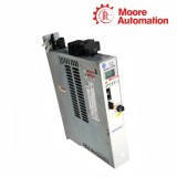
Copy| Product Name | Allen-Bradley 2198-P031 / 2198-P141 Kinetix 5700 Regenerative DC-bus Power Supplies |
| Item NO. | 2911893 |
| Weight | 0.1 kg = 0.2205 lb = 3.5274 oz |
| Category | AB |
| Brand | ALLEN-BRADLEY |
| Creation Time | 2026-09-30 |
The Allen-Bradley 2198-P031 / 2198-P141 pair comprises Kinetix 5700 regenerative dc-bus power supplies that convert 324…528 V three-phase ac input into the common dc bus used by attached inverter modules. The P031 is the 55 mm, 10 A ac-input class for smaller systems, while the P141 is an 85 mm, 47 A ac-input class supply for substantially higher connected inverter demand.
Power flow through 2198-P031 / 2198-P141 begins at the three-phase line and branch protection, passes through the controlled converter and precharge stages, and reaches the shared Kinetix 5700 bus links. A contactor-enable circuit coordinates the upstream main contactor, 24 V powers control electronics, and converter status over EtherNet/IP lets the motion system distinguish control readiness from actual dc-bus availability.
| Technical Item | 2198-P031 | 2198-P141 |
|---|---|---|
| Brand | Allen-Bradley | Allen-Bradley |
| Product Type | Kinetix 5700 regenerative DC-bus power supply | Kinetix 5700 regenerative DC-bus power supply |
| AC Input Voltage | 324…528 V three phase | 324…528 V three phase |
| Nominal Voltage Class | 480 VAC | 480 VAC |
| Nominal AC Input Current | 10 A | 47 A |
| DC-bus Output Class | 31 A class | 141 A class |
| Module Width | 55 mm | 85 mm |
| Approximate Weight | 4.33 kg | 6.91 kg |
| Line Frequency | 47…63 Hz class | 47…63 Hz class |
| Control Power | 24 VDC | 24 VDC |
| Contactor Interface | Contactor-enable relay and status path | Contactor-enable relay and status path |
| Network | EtherNet/IP status and configuration | EtherNet/IP status and configuration |
| Short-circuit Current Rating | Up to 200 kA with specified protection | Up to 200 kA with specified protection |
| Bus Connection | Kinetix 5700 shared DC-bus links | Kinetix 5700 shared DC-bus links |
| Mounting | Vertical open-type cabinet installation | Vertical open-type cabinet installation |
| Operating Temperature | 0…50 °C | 0…50 °C |
| Storage Temperature | −40…+70 °C | −40…+70 °C |
| Enclosure | IP20 open type | IP20 open type |
The controlled converter accepts 480 V-class three-phase input and develops the dc voltage shared across the connected bus-link assembly.
P031 serves the 10 A ac-input class, while P141 increases supply capacity to 47 A for a larger combined inverter and motion duty.
Energy returning from decelerating axes passes onto the common bus and through the system’s supported regenerative handling rather than remaining isolated at one drive.
The contactor-enable circuit allows the drive system to coordinate line connection with precharge and converter readiness.
Fuses or circuit breakers are selected from the exact supply rating and installed fault-current level, including the conditions required for the stated SCCR.
A live 24 V networked controller does not prove that three-phase input or dc-bus voltage is present; both states must be read during troubleshooting.
Sum the simultaneous motoring demand, regenerative profile, inverter losses and permitted overload of all axes. Then compare the result with the supply’s ac-input and dc-bus capacity rather than only the number of connected modules.
The 24 V control circuit and EtherNet/IP interface can be active while three-phase line power or the main contactor is absent. Check ac input, contactor enable, precharge state and bus voltage separately.
No. Their 10 A and 47 A input classes require catalog-specific branch protection and conductors. The available fault current and the desired SCCR also affect the approved protective-device choice.
Possible causes include an incorrect contactor sequence, excessive connected bus capacitance, a shorted bus, unstable input voltage or wiring errors. Isolate inverter sections and verify the line and bus before replacing the supply.
The supply expects the contactor-enable and status path to agree with its precharge sequence. A forced or incorrectly returned contactor state can prevent a safe and complete transition to an energized bus.
Capacity, width, weight, branch protection, input conductors and heat loss all change. Recalculate the system and update the physical panel and documentation rather than treating P141 as a same-frame upgrade.
Moore Automation keeps catalog numbers, label checks, quantity and dispatch evidence attached to the same order, with original products covered by a one-year warranty.
Model labels are reviewed.
Order references follow each item.
Coverage links to the supplied unit.
Condition is protected for transit.
| ABB3BSE066495R1 | Allen-Bradley1747-L514 | Bently Nevada146031-02 |
| EmersonKL2001X1-BC1 | GEIC655CHS506 | Siemens6ED1052-2FB08-0BA2 |
| Vibro-Meter601-041-A1 | WoodwardeasYgen-3200 | Allen-Bradley2198-C4075-ERS |
| Bently Nevada32000-28-05-15-080-03-02 | EmersonKJ4001X1-CC1 | GEIC600CB504 |
| ABB3HAC12928-1 | Allen-Bradley2198-D006-ERS3 | Bently Nevada330880-16-00-021-03-02 |
| EmersonKJ4001X1-CB1 | GEIC600CB507 | ABB3HAC14178-1 |
| Allen-Bradley2198-D012-ERS3 | Bently Nevada330881-16-00-200-06-02 | EmersonKJ3208X1-BK1 |
| GEIC600CB513 | ABB3HAC13398-2 | Allen-Bradley2198-D020-ERS3 |
| Bently Nevada330881-16-00-307-06-02 | EmersonSE4017P0 | GEIC600CB516 |
| ABB3HNA024284-001 | Allen-Bradley2198-D032-ERS3 | Bently Nevada168679-01-01-01-02-00-01 |
| EmersonVE4017P0 | GEIC600CB524 | ABB3HAC043073-001 |
| Allen-Bradley2198-D057-ERS3 | Bently Nevada168679-01-01-01-02-03-05-01-01-00-02-02 | EmersonVE4026 |
| GEIC600CB525 | ABB3HAC048232-001 | Allen-Bradley2198-D032-ERS4 |
| Bently Nevada141580-01 | EmersonKJ2006X1-BM1 | GEIC600CB526 |
| ABB3HAC058399-002 | Allen-Bradley2198-S086-ERS3 | Bently Nevada14700-01 |
| EmersonVE4021 | GEIC600CB527 | ABB3HAC058399-003 |
| Allen-Bradley2198-S160-ERS3 | Bently Nevada330103-00-03-10-01-05 | Emerson5X00717G01 |
| GEIC600CB536 | ABB3HAC037639-002 | Allen-Bradley2198-P070 |
| Bently Nevada330906-02-12-10-02-05 | Emerson5X00226G02 | GEIC600CB537 |
| ABB3HAC037835-001 | Allen-Bradley2198-P208 | Bently Nevada330104-00-04-10-02-05 |


Moore Automation Sales Team
Copyright © 2004–2026 www.mvme.cn. All rights reserved.
Disclaimer: Moore Automation Limited is an independent reseller and is not an authorized distributor or representative of the manufacturers featured on this website. Product names and trademarks belong to their respective owners.
No related record found