

Energy return
During deceleration, motor energy returns to the drive DC link instead of disappearing through the motor-output conductors.
Welcome to Moore Automation Limited




|
Copy and share this link on social network or send it to your friends
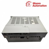
Copy| Product Name | Allen-Bradley 2198-E4055-ERS / 2198-E4075-ERS Kinetix 5100 400V-class servo drive |
| Item NO. | 2913243 |
| Weight | 0.1 kg = 0.2205 lb = 3.5274 oz |
| Category | AB |
| Brand | ALLEN-BRADLEY |
| Creation Time | 2026-10-08 |
KINETIX 5100 · 400V CLASS SERVO DRIVES
Allen-Bradley 2198-E4055-ERS / 2198-E4075-ERS are Kinetix 5100 servo drives for higher-output axes in the family’s high-voltage class. Each drive forms the controlled link between an EtherNet/IP motion controller and the motor assigned to that machine axis.
Allen-Bradley 2198-E4055-ERS / 2198-E4075-ERS occupy adjacent roles in the Kinetix 5100 range, but each must remain paired with its selected motor and cabinet design. The catalog number anchors the controller entry, braking arrangement and feedback cable set, preventing a higher-output axis from being commissioned with the neighboring drive configuration.

| Technical Item | 2198-E4055-ERS | 2198-E4075-ERS |
|---|---|---|
| Brand | Allen-Bradley | |
| Product Type | Kinetix 5100 400 V-class servo drive | |
| Brand Country | United States | |
| AC Input Voltage | 342...528 V rms, 3-phase | |
| Control Power Input | 24 V DC | |
| EtherNet/IP Ports | Two RJ45 ports, 10/100 Mbps | |
| EtherNet/IP Topology | Linear, ring, star | |
| Motor Feedback | 15-pin MFB connector | |
| Auxiliary Feedback | 10-pin AUX connector | |
| Continuous Output Power @ 480 V | 5.5 kW | 7.5 kW |
| Continuous Output Current | 24.80 A rms | 31.0 A rms |
| Peak Output Current | 37.65 A rms | 53.32 A rms |
| Shunt Arrangement | External passive shunt | |
| Power Loss @ 100% Rating | 342 / 363 W at 380 / 480 V | 467 / 494 W at 380 / 480 V |
| Approximate Weight | 5.0 kg (11.02 lb) | 10.0 kg (22.0 lb) |
| Drawing Dimension A | 120 mm (4.72 in.) | 141 mm (5.55 in.) |
| Drawing Dimension B | 37 mm (1.47 in.) | 16 mm (0.65 in.) |
| Drawing Dimension C | 59 mm (2.32 in.) | 35 mm (1.36 in.) |
| Drawing Dimension D | 209 mm (8.24 in.) | 225 mm (8.87 in.) |
| Drawing Dimension E | 273 mm (10.75 in.) | 312 mm (12.28 in.) |
The braking circuit handles energy returned by the motor during deceleration and must be completed before high-inertia motion is commissioned.
During deceleration, motor energy returns to the drive DC link instead of disappearing through the motor-output conductors.
Connect the specified passive shunt through the drive shunt path so returned energy has a controlled dissipation route.
Verify the shunt wiring and resistor selection before running a deceleration profile that can regenerate energy.
The primary motor loop and optional auxiliary measurement enter through different connectors and serve different control functions.
Terminate the motor feedback cable at MFB so the servo loop receives the motor position used for commutation and control.
Use AUX only for a supported secondary feedback signal; do not move the primary motor-feedback cable to this connector.
Keep both feedback assignments associated with the same axis entry while EtherNet/IP carries commands and status separately.
Use the rated output and current values, not only the common 400 V-class family name. E4055 is 5.5 kW with 24.80 A continuous output, while E4075 is 7.5 kW with 31.0 A continuous output.
These two drive sizes use an external passive-shunt arrangement. Include the required shunt path when the application needs regenerative energy handling; do not wire them as an internal-shunt drive.
The motor feedback connection is the 15-pin MFB connector, while the auxiliary feedback connection is the separate 10-pin AUX connector. Keep the two feedback functions separate during cable preparation and controller configuration.
Provide the 342...528 V rms three-phase AC input and the 24 V DC control-power input. The control supply is separate from the three-phase power that feeds the motor-output stage.
Each drive has two 10/100 Mbps RJ45 EtherNet/IP ports and supports linear, ring and star topologies. Use that network path for controller communication; it is not a substitute for the motor feedback or U/V/W connections.
Both drives have a 300 mm minimum recommended cabinet depth, and their full-load power loss differs by model. Confirm the physical depth and thermal load against the selected E4055 or E4075 rating before finalizing the enclosure.
 www.mvme.cn
Moore Automation sources automation and control components for customers worldwide while keeping the complete manufacturer reference visible through the order process.


Moore Automation Sales Team
Copyright © 2004–2026 www.mvme.cn. All rights reserved.
Disclaimer: Moore Automation Limited is an independent reseller and is not an authorized distributor or representative of the manufacturers featured on this website. Product names and trademarks belong to their respective owners.
No related record found