

Closed-loop drive path
2098-DSD-005 / 2098-DSD-030 convert single-phase AC input into closed-loop servo motor output while keeping power conversion, feedback, and control I/O separate.
Welcome to Moore Automation Limited

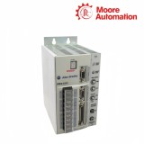


|
Copy and share this link on social network or send it to your friends
Copy| Product Name | Allen-Bradley 2098-DSD-005 / 2098-DSD-030 Ultra3000 non-indexing digital servo drives |
| Item NO. | 2913270 |
| Weight | 0.1 kg = 0.2205 lb = 3.5274 oz |
| Category | AB |
| Brand | ALLEN-BRADLEY |
| Creation Time | 2026-10-08 |
Allen-Bradley 2098-DSD-005 / 2098-DSD-030 are non-indexing Ultra3000 digital servo drives for the 230 V family, but they occupy widely separated power levels. DSD-005 supplies 0.5 kW at 230 V input, whereas DSD-030 supplies 3.0 kW and adds an internal passive-shunt circuit for regenerative energy. Both are panel-mounted components, but their supply protection and regenerative arrangements are not the same.
In 2098-DSD-005 / 2098-DSD-030, AC input feeds the DC bus and inverter, the motor-power terminals deliver controlled output, and motor feedback returns through a separate connector. Command, enable, and status signals enter through control I/O; they do not share the motor current path or substitute for the feedback connection. Ultraware commissioning retains the selected drive and motor data for that closed-loop path.
The electrical boundary changes substantially between 2098-DSD-005 / 2098-DSD-030. DSD-005 has 2.5 A continuous and 7.5 A intermittent output with no internal shunt resistor, while DSD-030 reaches 15 A continuous and 30 A intermittent and provides a 35 Ω internal shunt switched at 420 V DC. Their bus capacitance and overvoltage thresholds also belong to the individual power stage.
| Technical Item | 2098-DSD-005 / 2098-DSD-030 |
|---|---|
| Brand | Allen-Bradley |
| Product Type | Non-indexing digital servo drive |
| Brand Country | United States |
| Product Family | Ultra3000 |
| AC Input Voltage | 100–240 V rms, single-phase |
| AC Input Frequency | 47–63 Hz |
| Continuous Power at 230 V | 2098-DSD-005: 0.5 kW; 2098-DSD-030: 3.0 kW |
| Continuous Output Current | 2.5 A 0-peak / 15 A 0-peak |
| Intermittent Output Current | 7.5 A 0-peak / 30 A 0-peak |
| Main Input Current | DSD-030: 28 A rms nominal at 230 V |
| Bus Capacitance | DSD-005: 1410 µF; DSD-030: 2820 µF |
| Bus Overvoltage | DSD-005: 400 V DC; DSD-030: 452 V DC |
| Internal Shunt Resistance | DSD-005: none; DSD-030: 35 Ω |
| DSD-030 Shunt Thresholds | On at 420 V DC; off at 402 V DC |
| DSD-030 Internal Shunt Power | 50 W continuous; 4.5 kW peak |
| DSD-005 Energy Absorption | 93 J at 115 V input; 38 J at 230 V input |
| Motor Feedback | Dedicated feedback interface |
| Commissioning Software Family | Ultraware |


2098-DSD-005 / 2098-DSD-030 convert single-phase AC input into closed-loop servo motor output while keeping power conversion, feedback, and control I/O separate.
The rectifier and DC bus supply the inverter, which regulates motor current according to the configured position or velocity loop.
Motor sensing returns through the feedback connector so the Ultra3000 can compare commanded motion with actual motor response.
Enable, command, relay, and status functions use the control-I/O group rather than the high-current motor terminals.
DSD-005 uses a 400 V DC overvoltage threshold, while DSD-030 uses 452 V DC and an internal passive-shunt circuit.
DSD-030 switches its 35 Ω shunt at 420 V DC; DSD-005 has no internal shunt resistor and follows the smaller-drive regenerative arrangement.
A feedback, overvoltage, or enable problem should be traced in its own circuit before motor-power hardware is replaced.
Regarding 2098-DSD-005 / 2098-DSD-030, the DSD-030 has a much larger current stage, a different bus capacitance and overvoltage limit, and an internal 35 Ω shunt. Supply protection, motor cable, panel space, heat, feedback compatibility, and configured motor data all require separate checks.
DSD-005 has no internal shunt resistor and a 400 V DC bus-overvoltage boundary. Check the application’s regenerative energy and the approved external regenerative arrangement instead of assuming it has the DSD-030 internal shunt circuit. This distinction applies to 2098-DSD-005 / 2098-DSD-030.
Within 2098-DSD-005 / 2098-DSD-030, DSD-030 includes a 35 Ω internal shunt that turns on at 420 V DC and turns off at 402 V DC, with 50 W continuous and 4.5 kW peak capability. The load cycle must still remain within the drive and resistor limits.
For 2098-DSD-005 / 2098-DSD-030, consider the following. No. Control I/O carries enable, command, relay, and status signals. The feedback connector receives the motor sensor signals needed to close the servo loop, so moving feedback conductors to I/O would prevent correct commutation and regulation.
When 2098-DSD-005 / 2098-DSD-030 is involved, the model determines current limits, bus hardware, and power-stage behavior. A project based on the wrong catalog rating can present unsuitable motor and protection assumptions even if the communication link to the drive is successful.
Both are 100–240 V rms, 47–63 Hz single-phase Ultra3000 drives. Their common supply family does not make the output stages equal: DSD-005 is 2.5 A continuous and DSD-030 is 15 A continuous. This guidance covers 2098-DSD-005 / 2098-DSD-030.

Moore Automation supports industrial automation requirements through broad brand coverage, original-product supply, one-year warranty and coordinated quotation-to-delivery communication.
Send the complete model, quantity and destination for a precise quotation.


Moore Automation Sales Team
Copyright © 2004–2026 www.mvme.cn. All rights reserved.
Disclaimer: Moore Automation Limited is an independent reseller and is not an authorized distributor or representative of the manufacturers featured on this website. Product names and trademarks belong to their respective owners.
No related record found