

E4015 circuit
Keep the E4015 internal-shunt arrangement associated with its own drive position and do not copy an external-shunt termination into that position.
Welcome to Moore Automation Limited

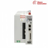

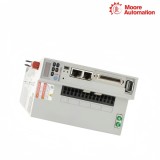

|
Copy and share this link on social network or send it to your friends
Copy| Product Name | Allen-Bradley 2198-E4015-ERS / 2198-E4020-ERS / 2198-E4030-ERS Kinetix 5100 400V-class servo drive |
| Item NO. | 2913246 |
| Weight | 0.1 kg = 0.2205 lb = 3.5274 oz |
| Category | AB |
| Brand | ALLEN-BRADLEY |
| Creation Time | 2026-10-08 |
KINETIX 5100 · 400V CLASS SERVO DRIVES
Allen-Bradley 2198-E4015-ERS / 2198-E4020-ERS / 2198-E4030-ERS are Kinetix 5100 servo drives for three successive single-axis motion duties. They share the same controller-oriented drive platform while assigning a distinct physical drive to each motor axis.
Allen-Bradley 2198-E4015-ERS / 2198-E4020-ERS / 2198-E4030-ERS cover three successive Kinetix 5100 axis duties while retaining one controller family. The complete catalog number must follow the physical drive because braking hardware and command configuration are commissioned at that individual axis position.

| Technical Item | 2198-E4015-ERS | 2198-E4020-ERS | 2198-E4030-ERS |
|---|---|---|---|
| Brand | Allen-Bradley | ||
| Product Type | Kinetix 5100 400 V-class servo drive | ||
| Brand Country | United States | ||
| AC Input Voltage | 342...528 V rms, 3-phase | ||
| Control Power Input | 24 V DC | ||
| EtherNet/IP Ports | Two RJ45 ports, 10/100 Mbps | ||
| EtherNet/IP Topology | Linear, ring, star | ||
| Motor Feedback | 15-pin MFB connector | ||
| Auxiliary Feedback | 10-pin AUX connector | ||
| Continuous Output Power @ 480 V | 1.5 kW | 2.0 kW | 3.0 kW |
| Continuous Output Current | 6.05 A rms | 7.42 A rms | 13.95 A rms |
| Peak Output Current | 15.11 A rms | 20.78 A rms | 26.08 A rms |
| Shunt Arrangement | Internal shunt resistor | External passive shunt | External passive shunt |
| Power Loss @ 100% Rating | 99 / 117 W at 380 / 480 V | 109 / 123 W at 380 / 480 V | 214 / 220 W at 380 / 480 V |
| Approximate Weight | 2.70 kg (5.95 lb) | 4.50 kg (9.92 lb) | 4.50 kg (9.92 lb) |
| Drawing Dimension A | 95 mm (3.74 in.) | 110 mm (4.33 in.) | 110 mm (4.33 in.) |
| Drawing Dimension B | 208 mm (8.20 in.) | 14 mm (0.55 in.) | 14 mm (0.55 in.) |
| Drawing Dimension C | 180 mm (7.09 in.) | 38 mm (1.50 in.) | 38 mm (1.50 in.) |
| Drawing Dimension D | 11 mm (0.43 in.) | 204 mm (8.02 in.) | 204 mm (8.02 in.) |
| Drawing Dimension E | — | 260 mm (10.24 in.) | 260 mm (10.24 in.) |
The regenerative circuit changes inside this three-model group, so the installed catalog number decides which braking path is wired.
Keep the E4015 internal-shunt arrangement associated with its own drive position and do not copy an external-shunt termination into that position.
Provide the specified external passive-shunt route for E4020 and verify the connection before regenerative operation.
Wire the E4030 external passive shunt as its own braking circuit rather than treating the neighboring model record as proof of connection.
The selected operating mode determines where a position command enters the drive, while motor feedback closes the same physical axis loop.
In PR mode, select and execute stored position records through the configured digital or communication command source.
In PT mode, route the pulse-train command through the assigned I/O terminals with the direction convention used by the controller.
After selecting the mode, confirm that MFB returns movement from the same motor that receives the commanded motion.
Compare the motor continuous and peak current with the E4015, E4020 or E4030 current column before selecting the drive. Their 1.5 kW, 2.0 kW and 3.0 kW values are separate axis limits, not selectable settings.
E4015 uses an internal shunt resistor, while E4020 and E4030 use the external passive-shunt path. Keep this distinction in the wiring plan because the DC energy path changes with the selected catalog number.
Each drive uses 342...528 V rms three-phase AC for the power stage and 24 V DC for control power. The controller network is a separate EtherNet/IP connection and does not replace either supply.
Motor feedback terminates at the 15-pin MFB connector and auxiliary feedback at the 10-pin AUX connector. Assign the correct feedback cable to each connector before configuring the axis.
Two 10/100 Mbps RJ45 EtherNet/IP ports support linear, ring and star topologies. Use the topology chosen for the controller network while retaining the full drive catalog number in the configuration.
The models have different 100% rated-load loss values even though each uses a 300 mm minimum recommended cabinet depth. Base the enclosure calculation on the actual E4015, E4020 or E4030 drive rather than the family label.
 www.mvme.cn
Stock checks and supplier coordination are organized around the complete model so available items can move from confirmation to dispatch without losing variant details.


Moore Automation Sales Team
Copyright © 2004–2026 www.mvme.cn. All rights reserved.
Disclaimer: Moore Automation Limited is an independent reseller and is not an authorized distributor or representative of the manufacturers featured on this website. Product names and trademarks belong to their respective owners.
No related record found