

01
Drive module definition
The complete drive catalog number and motor are selected in the Logix project so rating and feedback data match the installed hardware.
Welcome to Moore Automation Limited



|
Copy and share this link on social network or send it to your friends
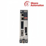
Copy| Product Name | Allen-Bradley 2198-C4015-ERS / 2198-C4020-ERS Kinetix 5300 Servo Drives |
| Item NO. | 2911607 |
| Weight | 0.1 kg = 0.2205 lb = 3.5274 oz |
| Category | AB |
| Brand | ALLEN-BRADLEY |
| Creation Time | 2026-09-28 |
480 V class · Frame 2 · Logix motion
Allen-Bradley 2198-C4015-ERS / 2198-C4020-ERS are 480 V class Frame 2 Kinetix 5300 single-axis servo drives. From 342…528 V three-phase input, they deliver 2.78 kW at 5.2 A rms and 3.90 kW at 7.3 A rms, with 7.4 A and 10.3 A continuous 0-pk values.
Axis commissioning for 2198-C4015-ERS / 2198-C4020-ERS is performed through a compatible Logix controller and Studio 5000 Logix Designer. The two Ethernet ports carry the Integrated Motion connection, while the drive display and navigation buttons provide local state and commissioning access.
Physical signal paths on 2198-C4015-ERS / 2198-C4020-ERS keep motor power, brake, feedback, digital/auxiliary feedback, 24 V control power, shunt and STO on dedicated connectors. This arrangement prevents the high-power U/V/W conductors from being treated as part of the feedback or network wiring.
| Technical Item | 2198-C4015-ERS | 2198-C4020-ERS |
|---|---|---|
| Brand | Allen-Bradley | |
| Product Type | Single-axis EtherNet/IP servo drive | |
| Brand Country | United States | |
| Product Series | Kinetix 5300 | |
| Input Voltage | 342…528 V AC, 3-phase | |
| Continuous Output Power | 2.78 kW | 3.90 kW |
| Continuous Output Current | 5.2 A rms | 7.3 A rms |
| Continuous Output Current (0-pk) | 7.4 A 0-pk | 10.3 A 0-pk |
| Frame Size | Frame 2 | |
| Approx. Dimensions (W × H × D) | 55 × 225 × 265 mm | |
| Motion Network | Integrated Motion over EtherNet/IP | |
| Network Media | 100BASE-TX, 100 Mbit/s, Cat5e | |
| Ethernet Ports | 2 × RJ45 | |
| Control Power | 24 V DC, separate connector | |
| Safety | Hardwired safe torque off | |
| Motor Feedback | 15-position MFB connector | |
| Digital / Auxiliary Feedback | 20-position spring-terminal connector | |
| Motor Brake | 2-position connector | |
| Mounting | Upright panel mount; zero-stack capable | |
| Airflow Clearance | 40 mm above and below | |
2198-C4015-ERS / 2198-C4020-ERS are configured as controller-owned motion axes rather than independent local speed controllers.
The complete drive catalog number and motor are selected in the Logix project so rating and feedback data match the installed hardware.
The drive module is assigned to the motion axis that produces commands and receives drive status.
The EtherNet/IP address and physical port connection establish the path used for commissioning and cyclic motion data.
2198-C4015-ERS / 2198-C4020-ERS connect each controlled axis through distinct power, feedback and actuator-support circuits.
Three-phase U/V/W output and protective earth leave through the motor-power connector and shield clamp.
Encoder and motor-thermal signals enter the 15-position MFB connector, separate from Ethernet traffic.
A two-position MBRK connector supplies the motor-brake circuit independently of the motor phases.
Use the complete drive catalog number and supported motor, then associate the module with the Logix motion axis that owns the commands.
Route U/V/W through the motor-power connector and terminate the motor cable shield at the designated shield clamp and protective-earth path.
Use the separate two-position MBRK connector; it is not part of the U/V/W motor phases or the feedback connector.
The dedicated CP input powers the drive control electronics separately from the 342…528 V AC power stage.
The display and MOD/NET indicators show module and protocol state, while the two port indicators show Ethernet link speed and activity.
Both are Frame 2, but continuous output changes from 5.2 A to 7.3 A rms, so the motor, protection and axis configuration must match the selected model.
Moore Automation combines stock visibility with worldwide supplier relationships to respond to industrial spare-parts enquiries across multiple brands.
Send the complete model number, required quantity and delivery destination for a focused quotation.


Moore Automation Sales Team
Copyright © 2004–2026 www.mvme.cn. All rights reserved.
Disclaimer: Moore Automation Limited is an independent reseller and is not an authorized distributor or representative of the manufacturers featured on this website. Product names and trademarks belong to their respective owners.
No related record found