

Command entry
Embedded I/O accepts the run, stop and reference signals assigned during commissioning, placing local field commands directly at the drive controller.
Welcome to Moore Automation Limited



|
Copy and share this link on social network or send it to your friends
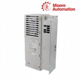
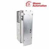
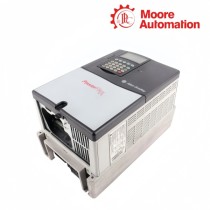
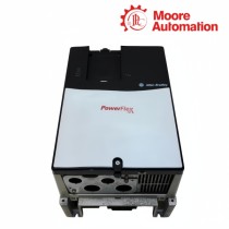
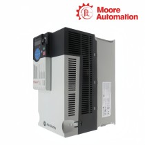
Copy| Product Name | Allen-Bradley 20F11GD8P0JA0NNNNN / 20F11GD027JA0NNNNN PowerFlex 753 IP54 AC Drives |
| Item NO. | 2911572 |
| Weight | 0.1 kg = 0.2205 lb = 3.5274 oz |
| Category | AB |
| Brand | ALLEN-BRADLEY |
| Creation Time | 2026-09-28 |
Built for enclosed motor-control locations, Allen-Bradley 20F11GD8P0JA0NNNNN and 20F11GD027JA0NNNNN are PowerFlex 753 AC drives with embedded I/O. They sit between a 480 V three-phase supply and a three-phase motor, converting fixed-frequency line power into controlled output for speed and torque regulation while local field signals enter and leave through the embedded I/O interface.
Within 20F11GD8P0JA0NNNNN and 20F11GD027JA0NNNNN, the AC input feeds a precharged DC link, the inverter produces variable-frequency motor power, and the dynamic-braking transistor can switch an external braking branch. Both use filtered, forced-air IP54 / NEMA Type 12 construction and ship without a HIM; the smaller unit uses Frame 2 hardware, while the higher-output unit moves to Frame 3.
| Technical Item | 20F11GD8P0JA0NNNNN | 20F11GD027JA0NNNNN |
|---|---|---|
| Brand | Allen-Bradley | |
| Product Type | PowerFlex 753 AC Drive, with Embedded I/O | |
| Brand Country | United States | |
| Corrosive Gas Protection and Cooling Type | Standard Protection, Forced Air | |
| Voltage Class | 480 VAC, 3 PH | |
| Output Current | 8 Amps, (Fr1 5HP ND, 3HP HD/Fr2 5HP ND, 5HP HD) | 27 Amps, 20HP ND, 15HP HD |
| Enclosure Type | IP54, NEMA Type 12 | |
| Input Type | AC Input with DC Terminals | |
| Frame Size | Frame 2 | Frame 3 |
| EMC Filtering Options | Filtered, CM jumper installed (preferred) | |
| Dynamic Braking | DB Transistor | |
| HIM | Blank (No HIM) | |
| Maximum Surrounding Air Temperature | 0...40 °C (32...104 °F) | |
| Storage Temperature | -40...70 °C (-40...158 °F) | |
| Relative Humidity | 5...95%, noncondensing | |
| Input Frequency Tolerance | 47...63 Hz | |
| Displacement Power Factor | 0.98 across the speed range | |
| Efficiency | 97.5% at rated current and nominal line voltage | |
| Output Voltage Range | 0 to rated motor voltage | |
| Output Frequency Range | 0...325 Hz at 2 kHz carrier; 0...590 Hz at 4 kHz carrier | |
| Maximum Short-Circuit Rating | 200,000 A RMS symmetrical | |
| Operating Shock | 15 g peak for 11 ms | |
| Operating Vibration | 1.000 mm displacement, 2 g peak | 1.000 mm displacement, 1.5 g peak |
The control and power sections perform different tasks but meet at the drive regulator.
Embedded I/O accepts the run, stop and reference signals assigned during commissioning, placing local field commands directly at the drive controller.
The rectifier and DC link establish an internal DC supply; the inverter then switches that energy into controlled three-phase motor output.
Drive state and assigned output signals leave through the control interface so the surrounding system can distinguish command state from power-stage operation.
The Type 12 enclosure protects the drive assembly, but frame size still governs mounting and airflow.
The 8 A drive uses Frame 2 and the 27 A drive uses Frame 3, so mounting holes and horizontal space are not interchangeable.
Cooling air must pass through the drive without cable bundles or adjacent equipment obstructing the inlet and exhaust areas.
The installed DB transistor is the switching element; a correctly rated resistor and its wiring remain external to the catalog-number configuration.

No. 20F11GD8P0JA0NNNNN uses Frame 2 and 20F11GD027JA0NNNNN uses Frame 3, so their mounting holes, outline and clearance allowance must be checked separately even though both are IP54 / Type 12 drives.
Both catalog numbers include embedded I/O for assigned field commands and returned status. Neither configuration includes a local HIM, so the required parameter-access method remains a separate commissioning choice.
The DB transistor is inside each drive, but the braking resistor is not. Its resistance, power rating and protection must match the selected drive and the actual deceleration energy.
The two drives have different current and frame ratings, and each provides separate normal-duty and heavy-duty motor ratings. The selected catalog number must match the motor current and required overload class, not only nominal kW.
Both filtered configurations are supplied with the CM jumper installed as the preferred arrangement. The jumper position must agree with the actual grounding system before power is applied.
Moore Automation supplies industrial automation and electronic components for current and legacy systems. Its product range covers control-system hardware, operator interfaces, drives, sensors and related spare parts, including discontinued and hard-to-find references.
 www.mvme.cn


Moore Automation Sales Team
Copyright © 2004–2026 www.mvme.cn. All rights reserved.
Disclaimer: Moore Automation Limited is an independent reseller and is not an authorized distributor or representative of the manufacturers featured on this website. Product names and trademarks belong to their respective owners.
No related record found