

DSD-075 current envelope
The 7.5 kW drive supplies 35 A continuously and 75 A intermittently, with 4290 µF bus capacitance.
Welcome to Moore Automation Limited



|
Copy and share this link on social network or send it to your friends
Copy| Product Name | Allen-Bradley 2098-DSD-075 / 2098-DSD-150 Ultra3000 high-power digital servo drives |
| Item NO. | 2913271 |
| Weight | 0.1 kg = 0.2205 lb = 3.5274 oz |
| Category | AB |
| Brand | ALLEN-BRADLEY |
| Creation Time | 2026-10-08 |
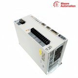
Allen-Bradley 2098-DSD-075 / 2098-DSD-150 are 230 V-class Ultra3000 non-indexing digital servo drives with three-phase main input and separate auxiliary control input. They provide 7.5 kW and 15 kW continuous output at 230 V, respectively, for high-current servo axes. The catalog pair therefore belongs to one control family without sharing the same branch-circuit or thermal design.
Inside 2098-DSD-075 / 2098-DSD-150, the main AC input charges the DC bus, the inverter produces the motor output, and an auxiliary AC input powers the control section. Motor feedback, control I/O, and motor power retain distinct connections, while the internal shunt network handles part of the regenerative energy returned to the bus. The auxiliary supply does not energize the motor.
The exact model matters when sizing protection and regeneration for 2098-DSD-075 / 2098-DSD-150. Continuous output rises from 35 A to 65 A and intermittent output from 75 A to 150 A; the larger DSD-150 also uses a lower shunt resistance, more bus capacitance, and a higher continuous internal-shunt rating. External shunt selection must also remain within the documented resistance and power limits.
| Technical Item | 2098-DSD-075 / 2098-DSD-150 |
|---|---|
| Brand | Allen-Bradley |
| Product Type | High-power non-indexing digital servo drive |
| Brand Country | United States |
| Product Family | Ultra3000 |
| Main AC Input | 100–240 V rms, three-phase |
| AC Input Frequency | 47–63 Hz |
| Continuous Power at 230 V | 2098-DSD-075: 7.5 kW; 2098-DSD-150: 15 kW |
| Main Input Current at 230 V | 30 A rms / 46 A rms |
| Continuous Output Current | 35 A 0-peak / 65 A 0-peak |
| Intermittent Output Current | 75 A 0-peak / 150 A 0-peak |
| Bus Capacitance | 4290 µF / 7520 µF |
| Internal Shunt Resistance | 16.5 Ω / 9.1 Ω |
| Shunt Switching | On at 420 V DC; off at 402 V DC |
| Bus Overvoltage | 452 V DC |
| Internal Shunt Power | DSD-075: 50 W/10 kW; DSD-150: 180 W/18 kW continuous/peak |
| External Shunt Minimum | 16.5 Ω / 9 Ω |
| Auxiliary Input Current | 1.0 A at 115 V; 0.5 A at 230 V nominal |
| Commissioning Software Family | Ultraware |
The 7.5 kW drive supplies 35 A continuously and 75 A intermittently, with 4290 µF bus capacitance.
The 15 kW drive supplies 65 A continuously and 150 A intermittently, with 7520 µF bus capacitance.
Both units use an auxiliary AC input rated at 1.0 A from 115 V or 0.5 A from 230 V nominal, separate from the main three-phase power.

Regenerative and power-cycling checks on 2098-DSD-075 / 2098-DSD-150 must use the model-specific shunt hardware and main-input current.
DSD-075 uses 16.5 Ω with 50 W continuous capability; DSD-150 uses 9.1 Ω with 180 W continuous capability.
Both switch the internal shunt at 420 V DC and release it at 402 V DC, with bus overvoltage at 452 V DC.
Separate main power, auxiliary power, feedback, and control-I/O checks prevent a missing auxiliary supply from being misdiagnosed as a failed motor-power stage.
For 2098-DSD-075 / 2098-DSD-150, consider the following. Record the complete model and the motor continuous/peak-current requirement. DSD-075 is 35/75 A 0-peak, while DSD-150 is 65/150 A; the bus capacitance and shunt hardware also change, so “Ultra3000 230 V” is not enough identification.
When 2098-DSD-075 / 2098-DSD-150 is involved, the auxiliary input powers the control section separately from the three-phase main input. It can support electronics and diagnostics, but it does not charge the main DC bus or provide motor-output energy.
Calculate returned energy against the internal shunt and any approved external shunt. DSD-075 and DSD-150 share the 420/402 V switching thresholds but have different resistance, continuous-power, peak-power, and external-resistor limits. This guidance covers 2098-DSD-075 / 2098-DSD-150.
On 2098-DSD-075 / 2098-DSD-150, no. Nominal main input current is 30 A for DSD-075 and 46 A for DSD-150 at 230 V, and their recommended protection differs. Protection should be selected for the exact drive and installation, not copied from the smaller model.
Feedback uses its own connector and low-level signal path. The motor terminals carry inverter output; probing or rewiring them as though they were feedback connections risks equipment damage and does not test the position-sensing circuit. The stated boundary applies to 2098-DSD-075 / 2098-DSD-150.
With 2098-DSD-075 / 2098-DSD-150 under review, keep the full 2098-DSD-075 or 2098-DSD-150 identity together with motor data, current limits, auxiliary-power arrangement, and shunt configuration. That record keeps replacement hardware aligned with the commissioned axis and prevents the higher-current DSD-150 hardware from being substituted against DSD-075 protection and shunt sizing.

Moore Automation supplies widely used industrial automation brands across control, motion, process automation and machinery-monitoring product categories.
Send the complete model, quantity and destination for a precise quotation.


Moore Automation Sales Team
Copyright © 2004–2026 www.mvme.cn. All rights reserved.
Disclaimer: Moore Automation Limited is an independent reseller and is not an authorized distributor or representative of the manufacturers featured on this website. Product names and trademarks belong to their respective owners.
No related record found