


Welcome to Moore Automation Limited

0
Loadding...
 

sales@mvme.cn    Phone: +86 18030175807

Home>YOKOGAWA>Yokogawa ANB11D-215 | Dual-Power Optical ESB Bus Node Unit
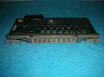
Yokogawa ANB11D-215 | Dual-Power Optical ESB Bus Node Unit

Yokogawa ANB11D-215 | Dual-Power Optical ESB Bus Node Unit Item NO.: 2928422

Write a Review
US$ 1.00
Quantity
Stock ( 28 )

Copy and share this link on social network or send it to your friends

Copy
Request Price & AvailabilitySend the part number and quantity. Our team will confirm stock, condition, lead time and the best quotation.
  • MOQ: 1 piece
  • International shipping
  • 1-year warranty on eligible items
  • Fast response during business hours
Product Name Yokogawa ANB11D-215 | Dual-Power Optical ESB Bus Node Unit
Item NO. 2928422
Weight 0.1 kg = 0.2205 lb = 3.5274 oz
Category YOKOGAWA
Brand YOKOGAWA
Creation Time 2026-10-30

Yokogawa ANB11D-215 | Moore Automation
Yokogawa

Yokogawa · optical ESB field I/O

Yokogawa ANB11D-215 | Dual-Power Optical ESB Bus Node Unit

Dual power execution · 5 km optical repeater · 100–120 V AC supply

01

Model Overview

Yokogawa ANB11D-215 is a dual-power optical ESB Bus Node Unit for CENTUM VP. Its selected optical-repeater execution supports the 5 km path while the D article retains redundant node power for the installed field I/O.

Inside the node, Yokogawa ANB11D-215 combines optical ESB communication, rack mounting and controller-defined I/O module positions. Both power feeds and both ends of the optical path should be documented independently so a single failure remains diagnosable.

During commissioning, Yokogawa ANB11D-215 should be brought online before individual field modules are tested. Optical link state, power redundancy, node recognition and module-slot status provide the sequence for separating media faults from I/O faults.

02

Technical Details

Brand
Yokogawa
Model
ANB11D-215
Product Name
Dual-power optical ESB Bus Node Unit
Country
Japan
System
CENTUM VP
Bus
Optical ESB
Power execution
Dual-redundant
Optical repeater
5 km execution
Supply
100–120 V AC
Explosion protection
Basic; none
Mounting
19-inch rack
Role
Remote field I/O node
03

Diagnostics and Protection

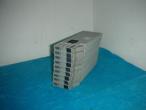
Yokogawa ANB11D-215 exposes power and optical-bus conditions that should be captured before any node reset. The diagnostic method preserves first-fault evidence, separates the affected layers and verifies the corrected path before the alarm is considered resolved.

Compare Both Power Feeds

Measure and identify each feed so a failed redundant path is not hidden by the healthy path. Capture the first LED pattern, system message and affected path before resetting anything, because later alarms may be consequences rather than the cause.

Inspect Optical State

Clean connectors and compare upstream/downstream link indications before replacing electronics. Isolate power, network and field-bus branches one at a time so protection or communication evidence is not lost by changing several conditions together.

Preserve Slot Diagnostics

Record which I/O modules disappeared and which remained visible through Yokogawa ANB11D-215. After correction, repeat the failed path test and document the restored state instead of accepting only a cleared alarm indication.

04

System Integration

The complete Yokogawa ANB11D-215 node is defined by optical route, controller position and installed module order. Each point below explains how the selected article works with the surrounding system rather than restating its specification rows.

Reserve the Node Address

Create the hardware position in the project before connecting the optical route. Give every controller, node, interface and bus segment a named position in the project before field wiring is released.

Map the 5 km Path

Document fibre endpoints, patch panels and loss points for Yokogawa ANB11D-215. The hardware tree, cabinet drawing and physical slot order must agree; otherwise a healthy component can appear missing at the system level.

Validate Installed Modules

Compare physical slot order and controller recognition before field loop testing. Close the integration check with representative signal and communication tests, then archive the accepted topology with the complete article string.

05

Customer Questions

01

How can redundant power on Yokogawa ANB11D-215 be proved rather than assumed?

With the node and bus stable, test each supply path to Yokogawa ANB11D-215 under the approved procedure and confirm the node remains observable. Record the result and feed identification separately.

02

What does the 5 km selection in Yokogawa ANB11D-215 require from the fibre route?

The optical route for Yokogawa ANB11D-215 still needs compatible endpoints, clean connectors, controlled bends and an acceptable loss budget; the 5 km execution is not permission to ignore connector or patch-panel loss.

03

What should be recorded before changing Yokogawa ANB11D-215?

Capture the complete Yokogawa ANB11D-215, node position, installed modules, bus connections, power arrangement and controller project before disconnecting the unit. This preserves slot and path ownership.

04

How should the bus be restored after fitting Yokogawa ANB11D-215?

With wiring and polarity checked, energize Yokogawa ANB11D-215, verify the node and bus indicators, then enable downstream sections in sequence. Confirm the controller recognizes each expected module before field testing.

05

What information prevents the wrong Yokogawa ANB11D-215 variant from being supplied?

State whether the node is single or dual power, the required bus or optical-repeater execution, supply voltage and explosion-protection code along with the complete Yokogawa ANB11D-215 string.

06

When is the bus cable or fibre more suspect than Yokogawa ANB11D-215?

If node power and configuration are correct but link status changes with cable movement or route substitution, test the cable, connector faces, bends and termination used by Yokogawa ANB11D-215 before replacing the node.

06

Service Support

Moore Automation

https://www.mvme.cn/

Moore Automation supports enquiry preparation by keeping article references, quantities and available supporting data organized.

The service does not extend into guaranteed technical resolution; it provides a traceable route for product and commercial questions.

Article reviewComplete codes are retained.
Quantity recordRequested amounts stay visible.
Supporting dataAvailable files can be coordinated.
Contact routeResponses use one named contact.
07

Related Models

Rockwell Automation2198-H003-ERS2
GEIS200VTCCH1C
MotorolaMVME55006E-0161
Rockwell Automation1766-L32AWAA
GEIS200TDBTH2A
Allen-Bradley2098-DSD-HV030
GEIS200TRPGH2B
GEDS200RTBAG2A
GEIC3600A1AD1C1D
GE ExcitationEX2000
GEIS210DTCIH1A
Rockwell Automation22B-A3P6N104
Rockwell Automation5069-L340ERM
MotorolaMVME147-022A
GEIS200EXCSG1A
GEDS200NATOG2A
GEIC630MDL326
GEDS200SLCCG2A
GEIS200STCIH1A
ABB Robotics3HAC17484-3
YokogawaADV169-PK0
EmersonKJ2005X1-MQ2
ABB Robotics3HAC046686-003
MotorolaMVME2604-1141A
ABB Robotics3HNA008029-00
TriconexTRICON 9666X
TriconexTricon 3008N
HIMAX-COM 01 001
Rockwell Automation2711P-B10C22D9P
GEIS200TRLYH1B
GEIC200UDR120
GEIC630MDL310
ABBSM560-S-FD-1-XC
YokogawaAAV141-S50/K4A00
GEIC200ALG262
MotorolaMVME162-510A
GEIC630MDL380
Rockwell Automation5069-L310ERM
GEIC3600SVSE1
GE ExcitationIS400TDBTH6A
GEIC3600STKK1J
GEIC630MDL327
GEDS200XDSAG1A
GEIC3600SVDC1F1C
GEIS200HFPAG1A
ABB Robotics3HAC17484-2/0
TriconexTRICON 9770X
GEIC200UDD212
GEDS200VPBLG1A
GEIS220PDIAH1A
GEIS200ERIOH1A
GEIS200ERBPG1A
ABB RoboticsACU-01B
GEHE800DIM310
MotorolaMVME61006E-0171
GEDS200TCPAG1A
Rockwell Automation1756-L81ES
GEIS220PAOCH1B
ProSoftPLX31-PND-MBS4
EmersonKJ3002X1-BB1
08

Sales Contact

Moore Automation

Send the complete model and requested quantity with your enquiry.

ManagerLeonia

No related record found

You May Also Like

Copyright © 2004–2026 www.mvme.cn. All rights reserved.

Disclaimer: Moore Automation Limited is an independent reseller and is not an authorized distributor or representative of the manufacturers featured on this website. Product names and trademarks belong to their respective owners.