

Choose the Correct Medium
Use ANB10S for electrical ESB or ANB11S for the documented optical path. Record the role of each physical port or fibre end before wiring, so cable labels and the saved network plan describe the same path.
Welcome to Moore Automation Limited





|
Copy and share this link on social network or send it to your friends
Copy| Product Name | Yokogawa ANB10S-315 / ANB11S-115 | ESB Bus Node Units |
| Item NO. | 2928421 |
| Weight | 0.1 kg = 0.2205 lb = 3.5274 oz |
| Category | YOKOGAWA |
| Brand | YOKOGAWA |
| Creation Time | 2026-10-30 |
Yokogawa · CENTUM VP ESB node units
Single power execution · Electrical / Optical ESB path · 100–120 V AC supply
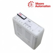
Yokogawa ANB10S-315 / ANB11S-115 are single-power ESB Bus Node Units for CENTUM VP field I/O. ANB10S-315 uses the electrical ESB path, while ANB11S-115 adds the optical ESB repeater execution selected for a 5 km optical link.
At the node boundary, Yokogawa ANB10S-315 / ANB11S-115 provide the mounting, supply and communication path for installed I/O modules. Their physical position, upstream and downstream bus connections and module-slot ownership must agree with the controller project.
For maintenance, Yokogawa ANB10S-315 / ANB11S-115 should be identified by full order string because the optical execution and reach on ANB11S are not visible from a generic node-unit description. Bus path, supply voltage and installed modules belong in the same record.
| Technical Item | ANB10S-315 | ANB11S-115 |
|---|---|---|
| Brand | Yokogawa | |
| Product Name | ESB Bus Node Unit | Optical ESB Bus Node Unit |
| Country | Japan | |
| Power execution | Single | |
| Bus path | Electrical ESB | Optical ESB repeater |
| Optical reach | Not applicable | 5 km execution |
| Supply | 100–120 V AC | |
| Explosion protection | Basic; none | |
| System role | Field I/O node | Remote optical field I/O node |
| Mounting | 19-inch rack | |
| Module organization | Controller-defined slot order | |
Yokogawa ANB10S-315 / ANB11S-115 occupy different ESB media boundaries, so the cable or fibre path must be selected before the node is mounted. The check therefore follows the complete path from interface ownership and physical media to addressing, link state and end-to-end communication.
Use ANB10S for electrical ESB or ANB11S for the documented optical path. Record the role of each physical port or fibre end before wiring, so cable labels and the saved network plan describe the same path.
Label both directions so a later break can be isolated without moving modules. Keep media type, connector condition, termination and route limits as installation checks; a software change cannot correct a damaged or mismatched physical link.
Match physical node position and slot order to the controller hardware definition. Acceptance should prove both local link indication and end-to-end traffic, with the tested path saved against the complete article record.
Installing Yokogawa ANB10S-315 / ANB11S-115 requires rack, earth, power, bus and slot checks in that order. The sequence is intentionally gated: article verification precedes mounting, mounting precedes termination, and commissioning begins only after the physical checks are complete.
Read the complete article and optical-reach requirement before mounting. Begin only after the complete article, mounting position and required companion hardware have been checked, and keep power isolated while the assembly is seated.
Land supply and bus or fibre connections, keeping bend and cleanliness limits visible. Do not force a connector, module or fibre that does not seat normally; recheck keying, alignment, bend radius and cabinet clearance before continuing.
Verify node recognition first, then each installed module and representative field channel. Energize the installation in a controlled order, preserve the first status evidence and record the final functional check against the installed article.
Choose ANB11S-115 in Yokogawa ANB10S-315 / ANB11S-115 when the documented ESB route requires the 5 km optical repeater execution; use ANB10S-315 for the electrical ESB path. Do not select only from rack appearance.
For the ANB11S portion of Yokogawa ANB10S-315 / ANB11S-115, keep caps fitted until connection, clean both fibre faces, respect bend limits and record the patch route before link testing.
Power at Yokogawa ANB10S-315 / ANB11S-115 does not confirm bus continuity. Check upstream and downstream connectors, optical or electrical path status, termination, node addressing and the controller configuration before replacing I/O modules.
Capture the complete Yokogawa ANB10S-315 / ANB11S-115, node position, installed modules, bus connections, power arrangement and controller project before disconnecting the unit. This preserves slot and path ownership.
With wiring and polarity checked, energize Yokogawa ANB10S-315 / ANB11S-115, verify the node and bus indicators, then enable downstream sections in sequence. Confirm the controller recognizes each expected module before field testing.
State whether the node is single or dual power, the required bus or optical-repeater execution, supply voltage and explosion-protection code along with the complete Yokogawa ANB10S-315 / ANB11S-115 string.
Moore Automation handles enquiries covering established control, drive, monitoring and instrumentation brands.
Brand and model fields remain separated so a similar family name does not replace the exact requested article.
Send the complete model and requested quantity with your enquiry.




Moore Automation Sales Team
Copyright © 2004–2026 www.mvme.cn. All rights reserved.
Disclaimer: Moore Automation Limited is an independent reseller and is not an authorized distributor or representative of the manufacturers featured on this website. Product names and trademarks belong to their respective owners.
No related record found