






Yokogawa AAV141-S50/K4A00 16-Channel 1-5 V Analog Input Module
Product Introduction
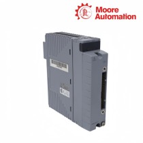
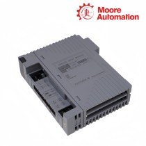
Yokogawa AAV141-S50/K4A00 is a 16-channel non-isolated differential 1-5 V DC input module in the CENTUM VP FIO family. Its main function is to receive field voltage signals and deliver their converted values to the control system through the FIO data path.
Each channel of Yokogawa AAV141-S50/K4A00 presents a high-impedance input, while the non-isolated design makes the field reference and common-mode voltage relevant to all connected sources. The differential measurement remains within its stated behavior when each source stays inside the documented ±1 V common-mode limit.
Signal routing for Yokogawa AAV141-S50/K4A00 passes through the ATK4A-00 adapter and KS cable to the AEA4D terminal board. The module refreshes data every 10 ms, while its 100 ms step response describes how the converted value settles after the field voltage changes.
Specification Details
| Brand | Yokogawa |
|---|---|
| Model | AAV141-S50/K4A00 |
| Product Name | 16-Channel 1-5 V Analog Input Module |
| Country | Japan (manufacturer) |
| Input Channels | 16, non-isolated differential |
| Input Signal | 1 to 5 V DC |
| Common-Mode Limit | ±1 V or less |
| Allowable Input Voltage | ±7.5 V |
| Input Resistance - Power On | 1 megohm or larger |
| Input Resistance - Power Off | 340 kilohms or larger |
| Accuracy | ±4 mV |
| Data Update Period | 10 ms |
| Step Response Time | 100 ms |
| Current Consumption | 350 mA at 5 V DC |
| Interface Option | ATK4A-00 KS cable interface adapter |
Voltage Signal Acquisition
AAV141-S50/K4A00 measures sixteen 1-5 V paths quickly, but useful accuracy depends on reference control and the distinction between channel update and full response.
Establish the signal reference
Map each transmitter output and return through the correct KS cable pair. A swapped reference or shared return problem can move multiple AAV141-S50/K4A00 readings at once.
Keep the common-mode voltage within ±1 V and document where the field reference meets the system reference.
Read timing correctly
The 10 ms update period is the internal data refresh, while the 100 ms step response describes the module response to a field change. Acceptance tests should use the correct criterion.
Trend a stable source long enough to separate module response from transmitter damping, control-system filtering and scan timing.
Protect the high-impedance input
With input resistance of at least 1 megohm during operation, leakage, moisture and contaminated terminations can influence a voltage signal without drawing obvious current.
Use clean connectors, verified insulation and a known voltage source when isolating a questionable channel.
KS Adapter Signal Routing
The /K4A00 assembly makes the adapter and cable part of the measurement chain, not an interchangeable accessory.
Confirm adapter identity
AAV141-S50/K4A00 includes ATK4A-00. Check the adapter nameplate and connector keying before installing the module in a cabinet prepared for another option.
Keep the adapter in the bill of material and spares record so a future replacement does not arrive as a bare module.
Trace channel order end to end
Compare the module channel list, KS cable conductors and remote termination numbering. A repeated offset usually points to mapping rather than sixteen bad inputs.
Test representative low and high channel numbers to expose a cable or connector alignment error quickly.
Control shields and grounds
Bond shields according to the cabinet design and avoid creating an unintended second reference path. Non-isolated channels make common wiring effects visible across a group.
If several channels move together, inspect grounding and common-mode voltage before replacing AAV141-S50/K4A00.
Product Questions
01Why do several AAV141-S50/K4A00 channels drift in the same direction?+
AAV141-S50/K4A00 uses non-isolated differential inputs, so a shared reference, shield or common-mode problem can affect a group; measure the field reference before changing the module.
02Why does AAV141-S50/K4A00 update data but respond slowly to a test step?+
AAV141-S50/K4A00 has a 10 ms data update and a 100 ms step response; also include transmitter damping and controller filtering in the observed end-to-end time.
03How can a channel-order error be isolated on AAV141-S50/K4A00?+
For AAV141-S50/K4A00, inject known voltages into separated channel numbers and trace them through ATK4A-00, the KS cable and the terminal schedule to locate an offset.
04What can cause a false high reading on AAV141-S50/K4A00?+
AAV141-S50/K4A00 should be checked for return continuity, common-mode voltage, leakage at the high-impedance input and the actual source voltage before calibration is changed.
05Can AAV141-S50/K4A00 be supplied without considering the K4A00 option?+
No. AAV141-S50/K4A00 includes the ATK4A-00 KS interface adapter, so a bare AAV141 or a pressure-clamp assembly is not the same delivered configuration.
06What should accompany an AAV141-S50/K4A00 enquiry?+
Send AAV141-S50/K4A00 exactly, quantity, destination, existing KS cable and terminal-board references, style/nameplate photo and the required warranty or inspection documents.
Customer Support
Moore Automation
https://www.mvme.cn
Moore Automation keeps customer communication focused on the requested item and the information needed to process an enquiry. Brand, full model, quantity, destination, reference photographs and requested documents can be reviewed in the same conversation.


No related record found