

Charge input
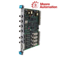
The sensor-side terminals receive the piezoelectric charge produced by the connected sensor.
Welcome to Moore Automation Limited



|
Copy and share this link on social network or send it to your friends
Copy| Product Name | Vibro-Meter IPC707 244-707-000-012-A2-B1-C10-D1-E5-F500-G2 IPC707 analogue signal conditioner |
| Item NO. | 2918992 |
| Weight | 0.1 kg = 0.2205 lb = 3.5274 oz |
| Category | VIBRO METER |
| Brand | OTHER PRODUCTS |
| Creation Time | 2026-10-13 |
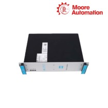
The Vibro-Meter IPC707 244-707-000-012-A2-B1-C10-D1-E5-F500-G2 is an analogue signal conditioner that converts the charge from a piezoelectric sensor into a voltage or current signal for a monitoring input. It is an Ex ia version with the selected transfer, filter and DIN-rail options encoded in the ordering string.
For IPC707 244-707-000-012-A2-B1-C10-D1-E5-F500-G2, the A2 code selects the explosive Ex ia environment, B1 selects the version without diagnostics, C10 selects a transfer sensitivity of 10, D1 selects μA/pC units without an integrator, E5 selects a 5 Hz high-pass filter and F500 selects a 500 Hz low-pass filter. G2 adds the MA130 DIN-rail adaptor.
For IPC707 244-707-000-012-A2-B1-C10-D1-E5-F500-G2, the sensor-side terminals receive the piezoelectric charge, while the signal-side terminals supply either a 3-wire voltage output or a 2-wire current output. The potted circuit is housed in aluminium, keeping the signal-conditioning function between the sensor cable and the monitoring system.
| Technical Item | IPC707 244-707-000-012-A2-B1-C10-D1-E5-F500-G2 |
|---|---|
| Brand | Vibro-Meter |
| Product Type | IPC707 analogue signal conditioner |
| Part Number | 244-707-000-012-A2-B1-C10-D1-E5-F500-G2 |
| Environment Code | A2, Ex ia |
| Diagnostics Code | B1, without diagnostics |
| Transfer Sensitivity | C10 / 10 |
| Transfer Units | D1, μA/pC without integrator |
| High-Pass Filter | E5 / 5 Hz |
| Low-Pass Filter | F500 / 500 Hz |
| Installation | G2, MA130 DIN-rail adaptor |
| Signal Output | Voltage, 3-wire or current, 2-wire |
| Enclosure | Potted electronics in aluminium housing |
IPC707 maps the charge signal from the sensor side to a usable analog signal on the monitoring side.
The sensor-side terminals receive the piezoelectric charge produced by the connected sensor.
The C10 and D1 codes define the selected transfer sensitivity and units before the output is produced.
A voltage output uses three-wire transmission, while a current output uses two-wire transmission on the signal side.
The ordering codes fix the signal-conditioning behavior in hardware rather than through a user software menu.
E5 and F500 define the 5 Hz high-pass and 500 Hz low-pass limits for the selected signal path.
A2 identifies the Ex ia version; the installation must preserve the certified sensor-side and signal-side circuit conditions.
G2 adds the DIN-rail adaptor, which changes the mechanical mounting arrangement without changing the transfer codes.
Which certified installation conditions must be confirmed for Vibro-Meter IPC707 244-707-000-012-A2-B1-C10-D1-E5-F500-G2?
Keep the A2 Ex ia selection, enclosure arrangement and associated certified circuit together when installing Vibro-Meter IPC707 244-707-000-012-A2-B1-C10-D1-E5-F500-G2. A general-purpose enclosure or an unverified barrier cannot be substituted merely because the signal wiring fits.
How should the two-wire or three-wire output be terminated on Vibro-Meter IPC707 244-707-000-012-A2-B1-C10-D1-E5-F500-G2?
Select the receiving input and terminal wiring to match the configured output mode of Vibro-Meter IPC707 244-707-000-012-A2-B1-C10-D1-E5-F500-G2. Voltage output uses the three-wire arrangement and current output uses the two-wire arrangement, so the monitor input must be changed with the mode rather than cross-wired.
How should E5 and F500 be checked when the measured band from Vibro-Meter IPC707 244-707-000-012-A2-B1-C10-D1-E5-F500-G2 is too narrow?
Verify the 5 Hz high-pass and 500 Hz low-pass selections in Vibro-Meter IPC707 244-707-000-012-A2-B1-C10-D1-E5-F500-G2 before changing the sensor. These are conditioner band limits; they do not change the mechanical response of the connected piezoelectric sensor.
What cable and charge-input checks help separate sensor noise from a Vibro-Meter IPC707 244-707-000-012-A2-B1-C10-D1-E5-F500-G2 fault?
Check the charge-signal cable, connector seating and shield path before replacing Vibro-Meter IPC707 244-707-000-012-A2-B1-C10-D1-E5-F500-G2. The conditioner receives the sensor charge and then produces the selected analog output, so a wiring fault can look like a filter or output-mode problem.
Can the G2 DIN-rail adaptor be removed after mounting Vibro-Meter IPC707 244-707-000-012-A2-B1-C10-D1-E5-F500-G2?
Keep the G2 mounting arrangement intact for Vibro-Meter IPC707 244-707-000-012-A2-B1-C10-D1-E5-F500-G2 unless the enclosure layout is rechecked. Removing the adaptor changes the mechanical support and cable entry, not just the appearance of the installation.
Which commissioning sequence should be followed after Vibro-Meter IPC707 244-707-000-012-A2-B1-C10-D1-E5-F500-G2 starts with an output alarm?
Confirm the selected two-wire/three-wire mode, filter settings and sensor charge path in that order for Vibro-Meter IPC707 244-707-000-012-A2-B1-C10-D1-E5-F500-G2. Then check the A2 certified circuit and the receiving input range before declaring the conditioner defective.
Moore Automation uses a model-first enquiry record: the manufacturer, complete code and requested quantity stay together before the item is prepared. The record is then used for the visible packing check.
Send the complete model and requested quantity with your enquiry.


Moore Automation Sales Team
Copyright © 2004–2026 www.mvme.cn. All rights reserved.
Disclaimer: Moore Automation Limited is an independent reseller and is not an authorized distributor or representative of the manufacturers featured on this website. Product names and trademarks belong to their respective owners.
No related record found