

J1 measurement inputs
J1 carries analog inputs for dynamic measurement channels 1 to 4.
Welcome to Moore Automation Limited




|
Copy and share this link on social network or send it to your friends
Copy| Product Name | Vibro-Meter IOC4T 200-560-000-114 VM600 IOC4T input/output card |
| Item NO. | 2918990 |
| Weight | 0.1 kg = 0.2205 lb = 3.5274 oz |
| Category | VIBRO METER |
| Brand | OTHER PRODUCTS |
| Creation Time | 2026-10-13 |
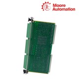
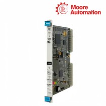
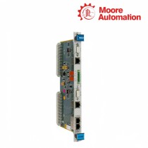
The Vibro-Meter IOC4T 200-560-000-114 is a VM600 input/output card associated with an MPC4 machinery protection card. It brings dynamic, tachometer and digital control signals into the rack and routes buffered sensor signals, DC outputs and relay contacts back to field wiring.
For IOC4T 200-560-000-114, the 200-560-000-114 variant is the later RoHS-compliant IOC4T version with 50 ohm buffered dynamic-signal output impedance. Its rear connectors separate the measurement inputs, tachometer and relay contacts, analog outputs, raw buffered outputs and DSI control signals rather than combining them into one terminal group.
For IOC4T 200-560-000-114, the card occupies a 6U, 20 mm-wide slot and connects to the MPC4 through the VM600 rack infrastructure. Its J1, J2 and J3 connectors therefore define the field-side boundary while the associated MPC4 performs the machinery-protection processing.
| Technical Item | IOC4T 200-560-000-114 |
|---|---|
| Brand | Vibro-Meter |
| Product Type | VM600 IOC4T input/output card |
| Associated Card | MPC4 machinery protection card |
| Version | 200-560-000-114 |
| Height | 6U / 262 mm |
| Width | 20 mm |
| Depth | 125 mm |
| Dynamic Inputs | Channels 1 to 4 |
| Tachometer Inputs | Channels 1 to 2 |
| Relay Outputs | RL1 to RL4 |
| Analog DC Outputs | DC outputs 1 to 4 |
| Buffered Raw Outputs | Dynamic channels 1 to 4 |
| Input Impedance | 50 ohm buffered output version |
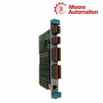
IOC4T separates its rear-panel connections according to the signal class handled by the MPC4 pair.
J1 carries analog inputs for dynamic measurement channels 1 to 4.
J2 carries tachometer inputs, relay outputs and DSI control signals.
J3 carries DC analog outputs and buffered raw sensor outputs for the dynamic channels.
The IOC4T is the rack-side interface between field wiring and the MPC4 processing card.
The 6U card sits in the VM600 rack and exchanges data with the associated MPC4 through the rack connection.
Sensor and tachometer signals enter at the rear connectors before the MPC4 applies the configured protection logic.
The 200-560-000-114 revision is the later 50 ohm buffered-output version, so the exact card suffix must be retained in the system record.
Which MPC4 pairing and rack position should be confirmed before wiring Vibro-Meter IOC4T 200-560-000-114?
Confirm that Vibro-Meter IOC4T 200-560-000-114 is installed as the matching I/O partner for the specified MPC4 in the VM600 rack. Check the card position and rear connector access before landing any field wire, because IOC4T is not a standalone protection processor.
Which connector assignment should be followed for Vibro-Meter IOC4T 200-560-000-114?
Keep the connector functions separate on Vibro-Meter IOC4T 200-560-000-114: J1 carries analog inputs, while J2/J3 carry the documented tachometer, relay, DSI and analog-output groups. Label each cable before termination so a field signal is not landed on a relay or output pin group.
What load and impedance check is needed for the buffered outputs of Vibro-Meter IOC4T 200-560-000-114?
Match the receiving input to the 50 Ω buffered-output version of Vibro-Meter IOC4T 200-560-000-114. Do not connect the load as if it were the earlier 2 000 Ω variant; the impedance selection affects signal level and the permitted termination.
What rear access is needed to service the connectors of Vibro-Meter IOC4T 200-560-000-114?
Leave access for the rear J1/J2/J3 plugs and the rack wiring bend radius around Vibro-Meter IOC4T 200-560-000-114. The card routes field signals through the rear interface, so a crowded cable channel can create a connector or strain fault even when the front MPC4 is healthy.
Which path should be traced when a relay or DSI indication from Vibro-Meter IOC4T 200-560-000-114 is missing?
Trace the assigned connector group and the paired MPC4 configuration before replacing Vibro-Meter IOC4T 200-560-000-114. Verify the J2/J3 termination and the VM600 rack path separately, since the interface card only routes the signal and does not create the protection decision.
Can an earlier IOC4T version replace Vibro-Meter IOC4T 200-560-000-114 without checking the MPC4 card pair?
No; preserve the 200-560-000-114 version and verify the complete MPC4/IOC4T pair for Vibro-Meter IOC4T 200-560-000-114. The buffered-output impedance and connector assignment must match the installed processing card and field wiring.
Moore Automation handles automation enquiries by retaining the manufacturer and full model string in the same record. This avoids separating a product family name from the exact ordered variant during handoff.
Send the complete model and requested quantity with your enquiry.
Moore Automation Sales Team
Copyright © 2004–2026 www.mvme.cn. All rights reserved.
Disclaimer: Moore Automation Limited is an independent reseller and is not an authorized distributor or representative of the manufacturers featured on this website. Product names and trademarks belong to their respective owners.
No related record found