




GE Fanuc IC610MDL125 / IC610MDL158 / IC610MDL185 Series One I/O Modules
A grouped Series One comparison covering a 115 VAC input module, a 24 VDC source-output module and a UL-listed 115 VAC output module.
Product Overview
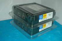
GE Fanuc IC610MDL125, IC610MDL158 and IC610MDL185 are Series One discrete I/O modules: an eight-point 115 VAC input, a sixteen-point 24 VDC source output and a six-point UL-listed 115 VAC output respectively.
All three modules occupy the Series One I/O environment, but their signal direction, field voltage, channel grouping, termination and protection are different; none is a substitute for another.
IC610MDL125: Receives eight 115 VAC discrete input signals in two groups of four.
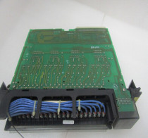
IC610MDL158: Sources sixteen 5–24 VDC discrete loads through two fused groups and a removable terminal board.
IC610MDL185: Switches six 97–132 VAC loads through two fused groups and carries the UL listing documented for this module.
Technical Specifications
| Brand | GE Fanuc |
|---|---|
| Model | IC610MDL125 / IC610MDL158 / IC610MDL185 |
| Product Type | Discrete I/O Modules |
| Country | United States |
| Platform | Series One |
| IC610MDL125 function | 8-point 115 VAC discrete input |
| IC610MDL125 operating range | 97–132 VAC, 47–63 Hz |
| IC610MDL125 input current | 15 mA at 60 Hz; 11.5 mA at 50 Hz |
| IC610MDL125 thresholds | ON above 80 VAC; OFF below 20 VAC |
| IC610MDL125 response | 10–30 ms OFF-to-ON; 10–60 ms ON-to-OFF |
| IC610MDL125 weight | 140 g / 5 oz |
| IC610MDL158 function | 16-point, 5–24 VDC source output |
| IC610MDL158 load | 0.5 A typical per point at 24 VDC; 0.1 A minimum |
| IC610MDL158 grouping | Two groups of eight; one 5 A fuse per group |
| IC610MDL158 termination | Removable screw-terminal board; one AWG 12 or two AWG 14 wires per terminal |
| IC610MDL185 function | 6-point, UL-listed 115 VAC output |
| IC610MDL185 operating range | 97–132 VAC, 47–63 Hz |
| IC610MDL185 load | 0.5 A maximum per point; 25 mA minimum recommended load |
| IC610MDL185 grouping | Two groups of three with a common connection; one 5 A fuse per group |
Signal Types and Channel Organization
IC610MDL125 receives contact states through optically isolated 115 VAC input circuits, filtering the field signal before its logic state reaches the Series One CPU.
IC610MDL158 drives DC loads from two fused groups of eight source outputs, while IC610MDL185 switches 115 VAC loads through two fused groups of three solid-state outputs.
The three modules also differ in indication and protection: the input LEDs represent sensed field states, while the two output modules indicate commanded logic states and protect their output groups with fuses.
Field Wiring and Protection


IC610MDL125 divides eight inputs into two groups of four and recognizes an ON state above 80 VAC and an OFF state below 20 VAC.
IC610MDL158 uses two 5 A fused output groups on its removable terminal board. IC610MDL185 also uses two 5 A groups, but switches six 97–132 VAC loads rather than DC loads.
The IC610MDL125 input circuitry uses optical coupling, while IC610MDL158 and IC610MDL185 use different DC and AC output circuits; their commons and load paths must follow the exact wiring drawing.
IC610MDL125 / IC610MDL158 / IC610MDL185 FAQ
Can IC610MDL125 / IC610MDL158 / IC610MDL185 replace one another?
No. IC610MDL125 senses 115 VAC, IC610MDL158 sources DC loads and IC610MDL185 switches 115 VAC loads.
How are field commons arranged on IC610MDL125 / IC610MDL158 / IC610MDL185?
IC610MDL125 uses two input groups of four, IC610MDL158 uses two output groups of eight, and IC610MDL185 uses two AC-output groups of three with a common connection.
Which terminals and conductors apply to IC610MDL125 / IC610MDL158 / IC610MDL185?
Use the wiring arrangement for the exact module; IC610MDL158 specifically uses a removable terminal board accepting one AWG 12 or two AWG 14 conductors per terminal.
How should the load be matched for IC610MDL125 / IC610MDL158 / IC610MDL185?
Treat IC610MDL125 as an input. Keep IC610MDL158 within its DC point and group limits, and keep IC610MDL185 AC loads within 0.5 A per point and above the 25 mA recommended minimum.
Which protection devices belong to IC610MDL125 / IC610MDL158 / IC610MDL185?
IC610MDL158 has two 5 A group fuses and IC610MDL185 has two soldered 5 A group fuses; the input module has no output-group fuse function.
How should commons be checked on IC610MDL125 / IC610MDL158 / IC610MDL185?
Trace each terminal group against the module-specific wiring information because the AC inputs, DC source outputs and AC outputs use different group arrangements.
Multi-brand supply scope
The available product range spans established automation manufacturers, helping maintenance teams consolidate enquiries that cross more than one control platform.



No related record found