

One rack family
All three are Series Six rack modules using backplane resources.
Welcome to Moore Automation Limited




|
Copy and share this link on social network or send it to your friends
Copy| Product Name | GE Fanuc IC600BF830 / IC600BF831 / IC600BF832 Series Six I/O Modules |
| Item NO. | 2906544 |
| Weight | 0.1 kg = 0.2205 lb = 3.5274 oz |
| Category | GE |
| Brand | GE |
| Creation Time | 2026-09-08 |
A combined reference for an advanced I/O-chain receiver and two high-density discrete input modules with different field-signal classes.
IC600BF830, IC600BF831 and IC600BF832 belong to the GE Fanuc Series Six modular I/O family, but they serve different parts of the control signal path. IC600BF830 receives and continues an I/O chain at the rack while making chain condition available to the CPU. IC600BF831 and IC600BF832 are discrete input modules that transfer field states into the rack backplane.
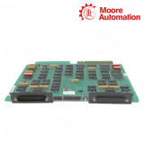
The IC600BF830 Advanced I/O Receiver carries upstream and downstream I/O traffic through two 37-pin connectors. Separate switch selections assign its input-status and output-control addresses, allowing CPU logic to react to a failed downstream power supply, a broken chain cable and supported parity conditions. Resistor-pack placement adapts the receiver for an intermediate rack or the final rack on the chain.
IC600BF831 and IC600BF832 each provide 32 high-density input points, but they belong to different electrical classes. IC600BF831 is the 10–50 Vdc input version with local indication; IC600BF832 is the 115 Vac input version. Their similar catalog sequence does not make the receiver, DC input and AC input functions interchangeable.
All three are Series Six rack modules using backplane resources.
IC600BF831 handles DC input circuits; IC600BF832 handles AC input circuits.
IC600BF830 manages the serial I/O-chain path rather than field input points.
| Specification | IC600BF830 | IC600BF831 | IC600BF832 |
|---|---|---|---|
| Brand | GE Fanuc | ||
| Product Type | Advanced I/O Receiver | High-density DC input module with status indicators | High-density AC input module with status indicators |
| Country | United States | ||
| System Family | Series Six / Series Six Plus modular I/O | ||
| Rack Position | Series Six I/O rack; installed in the leftmost slot | Series Six I/O rack, Model 60 CPU I/O slot or Series Six Plus CPU rack | Series Six I/O rack or Series Six Plus CPU rack |
| Primary Function | Receives and continues the serial I/O chain and reports addressed chain faults | Transfers 10–50 Vdc field-input states to the Series Six backplane | Transfers 115 Vac field-input states to the Series Six backplane |
| Point or Interface Configuration | Two 37-pin I/O-chain connectors for upstream and downstream communication | 32 inputs in four groups of eight; one common return for all inputs | 32 inputs in four isolated groups of eight; one neutral/common per group |
| Field Signal | Serial I/O-chain data and receiver diagnostic status | 10–50 Vdc, selectable sink or source operation | 115 Vac, 47–63 Hz; ON 80–132 Vac, OFF 0–30 Vac |
| Response | Receiver watchdog, chain-fault and parity diagnostic processing | 50 µs with filter out or 10 ms with filter in, individually selectable per input | ON delay 10–20 ms; OFF delay 20–40 ms |
| Rack Power | 5 Vdc, 680 mA typical and 1.2 A maximum | 5 Vdc, 200 mA maximum or 4 load units | 5 Vdc, 104 mA maximum |
| Isolation | I/O-chain receiver interface rather than a field-input isolation circuit | 2,000 Vdc for 1 second maximum; 240 Vac continuous maximum | 240 Vdc or 50/60 Hz Vac continuous; 1,500 V peak non-repetitive transient |
| Indicators and Setup | 12 diagnostic LEDs, external RESET, address and option DIP switches, and intermediate/final-rack resistor-pack positions | Input status indicators; jumpers select sink/source and inverted/non-inverted data; DIP switches select each input filter | One LED per active input; backplane DIP switches reserve four consecutive input groups |
| Circuit Board Dimensions | 8.15 × 11.0 × 1.20 in (208 × 280 × 31 mm) | 8.15 × 11.0 in (208 × 280 mm) | |
| Faceplate Dimensions | 12.46 × 1.175 in (317 × 30 mm) | ||
| Environment | Operating 0 to 60°C; storage −20 to +80°C; 5–95% RH non-condensing | ||

The CPU can read receiver condition through the selected input address and send control through a separately selected output address.
Chain power and cable failures are reported; the required CPU software level also permits responses to input and output parity faults.
I/O data passes through the receiver even when its rack is not functional, including when the local rack power supply is off.
The two resistor packs occupy one socket pair for an intermediate rack and another pair when the receiver terminates the I/O chain.
Faceplate LEDs retain selected fault conditions until the fault clears and the RESET control or CPU logic resets the indication.
Remove rack and field power before handling the module. The IC600BF832 field terminals can remain energized from external devices even when the rack power supply is off.
Install IC600BF830 in the leftmost slot of the I/O rack. IC600BF831 and IC600BF832 occupy a Series Six I/O position addressed from the rack backplane.
For IC600BF830, place resistor packs in U7 and U8 for an intermediate rack or U12 and U50 for the final rack, then set the required input, output and option DIP switches. For IC600BF832, set the backplane DIP switches so the first eight terminals map to the first of four consecutive input groups.
Use the Series Six extraction/insertion tool to seat the board in the card slot. Guide the faceplate over the board so the lower terminals mate, then secure the top and bottom thumbscrews.
On IC600BF830, connect the upper 37-pin port to the upstream rack or CPU and use the lower port for the downstream I/O chain when required. On IC600BF832, wire inputs 1–8 of each group to that group’s independent neutral/common.
Restore power only after wiring and hardware settings are complete. Confirm IC600BF830 chain and diagnostic LEDs, then verify the mapped DC or AC input states for IC600BF831 and IC600BF832.
No. The three modules perform different receiver, DC-input and AC-input functions, so their connections and control roles are not interchangeable.
Use the complete faceplate number and connected wiring. I/O-chain cables identify IC600BF830, while the documented field voltage separates IC600BF831 from IC600BF832.
Confirm chain continuity, termination, addresses and diagnostic LEDs for IC600BF830. Prove every mapped input with the correct field signal for IC600BF831 or IC600BF832.
IC600BF830 carries receiver address and chain-position choices. IC600BF831 and IC600BF832 instead depend on field-input mapping, commons and voltage class.
IC600BF830 provides addressed receiver status and chain diagnostics. IC600BF831 and IC600BF832 acquire field input states rather than receiving the I/O chain.

Moore Automation supplies industrial automation spare parts across PLC and DCS hardware, I/O modules, drives, operator interfaces, communication equipment and power components. Its multi-brand product range covers both established and current control platforms used for maintenance, replacement and plant inventory requirements.
The company states 100% original products, fast delivery, a 1-year warranty and a 12-hour online response for sales enquiries. These service commitments support customers sourcing regular and difficult-to-find industrial automation components.



Moore Automation Sales Team
Copyright © 2004–2026 www.mvme.cn. All rights reserved.
Disclaimer: Moore Automation Limited is an independent reseller and is not an authorized distributor or representative of the manufacturers featured on this website. Product names and trademarks belong to their respective owners.
No related record found