

K20 to K26
Seven plug-in relays each expose two Form C contact sets, producing the board’s DPDT group.
Welcome to Moore Automation Limited


|
Copy and share this link on social network or send it to your friends
Copy| Product Name | GE DS200RTBAG1A RTBA Relay Terminal Board |
| Item NO. | 2940234 |
| Weight | 0.1 kg = 0.2205 lb = 3.5274 oz |
| Category | GE |
| Brand | GE |
| Creation Time | 2026-11-17 |
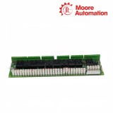
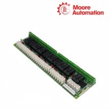
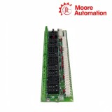
GE DS200RTBAG1A is an optional RTBA relay terminal board installed inside a GE drive or exciter cabinet. It expands control outputs through ten plug-in relays that can be driven by pilot relays on the 531X307LTB LAN I/O Terminal Board or by external user wiring.
The contact organization on GE DS200RTBAG1A separates K20 through K26 from K27 through K29. K20–K26 provide two Form C contact sets per relay, while K27–K29 provide four Form C contact sets per relay, giving the board both DPDT and 4PDT output groups.
As the G1 hardware group, GE DS200RTBAG1A uses 110 V dc relay coils. Berg-type jumpers select defined coil-source and contact arrangements; the application record and board jumper positions must therefore be compared together when the relay terminal board is identified.
| Specification | DS200RTBAG1A |
|---|---|
| Brand | GE |
| Functional acronym | RTBA |
| Product type | Relay terminal board |
| Installation location | Drive or exciter cabinet |
| Board status | Optional cabinet board |
| Total relays | 10 |
| K20–K26 | Seven relays, two Form C contacts each |
| K27–K29 | Three relays, four Form C contacts each |
| Relay group | G1 |
| Coil voltage | 110 V dc |
| Internal drive source | 531X307LTB pilot relays |
| External drive | User wiring supported |
| Configurable hardware | Berg-type JP jumpers |
| Primary manual | GEI-100167B |
GE DS200RTBAG1A divides ten relay outputs into two contact-density groups.
Seven plug-in relays each expose two Form C contact sets, producing the board’s DPDT group.
Three plug-in relays each expose four Form C contact sets, producing the higher-density 4PDT group.
Normally open, common and normally closed points are identified by relay and contact number on the terminal board.
GE DS200RTBAG1A sits between cabinet control signals and field relay contacts.
The RPL interface carries pilot inputs from the 531X307LTB board to the RTBA relay coils.
Selected relays can be picked up from an external voltage source through the corresponding coil terminals and jumper setting.
The Form C contacts leave the board through named terminal points for external control or protection circuits.
GE DS200RTBAG1A is the G1 version with 110 V dc coils. G2 uses 24 V dc and G3 uses 115 V ac, so the base RTBA name is not enough for coil-supply matching.
GE DS200RTBAG1A uses K27, K28 and K29 as four-Form-C relays. K20 through K26 have two Form C contact sets each.
GE DS200RTBAG1A supports external user drive for defined relay circuits when the coil-source terminals and JP jumper positions are set for that path.
GE DS200RTBAG1A jumper positions should be recorded against the application data before any change because most selections are factory set for the cabinet circuit.
GE DS200RTBAG1A is described as an optional relay terminal board. Its presence depends on the drive or exciter cabinet configuration.
GE DS200RTBAG1A uses the relay number plus contact number and NO, CM or NC suffixes, allowing each Form C set to be traced to its relay.
https://www.mvme.cn
Moore Automation uses complete identification rather than shortened family names when preparing industrial automation enquiries. This approach keeps option codes, hardware groups and board revisions visible where they affect the requested item.


Moore Automation Sales Team
Copyright © 2004–2026 www.mvme.cn. All rights reserved.
Disclaimer: Moore Automation Limited is an independent reseller and is not an authorized distributor or representative of the manufacturers featured on this website. Product names and trademarks belong to their respective owners.
No related record found