

Non-contact target response
The coil in 330710-004-054-50-02-05 creates an eddy-current field at the conductive target. A change in shaft-to-tip distance changes probe impedance without requiring physical contact.
Welcome to Moore Automation Limited




|
Copy and share this link on social network or send it to your friends
Copy| Product Name | Bently Nevada 330710-004-054-50-02-05 | 3300 XL 11 mm Proximity Probe |
| Item NO. | 2925606 |
| Weight | 0.1 kg = 0.2205 lb = 3.5274 oz |
| Category | BENTLY NEVADA |
| Brand | Bently Nevada |
| Creation Time | 2026-10-20 |
Bently Nevada · 3300 XL 11 mm proximity system
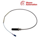
Bently Nevada 330710-004-054-50-02-05 is an armored 3300 XL 11 mm proximity probe with an M16 x 1.5 threaded case. It forms the sensing end of a matched eddy-current transducer system, establishing the non-contact field at a conductive target and returning the gap-dependent response through its integral cable.
The mechanical code of 330710-004-054-50-02-05 defines 4 mm of unthreaded length and a 54 mm overall case. This relationship positions the 10.7 mm probe tip ahead of the threaded body while the armor protects the cable as it leaves the case.
With a five-metre total lead and the standard ClickLoc connector, 330710-004-054-50-02-05 connects to the five-metre 3300 XL 11 mm Proximitor Sensor. The probe, its complete cable length and the matched electronics operate as one calibrated path rather than as independently interchangeable cable segments.
Bently Nevada 330710-004-054-50-02-05 performs the first stage of the 3300 XL 11 mm measurement chain. Its probe tip responds to target distance, while the matched Proximitor Sensor converts the returned impedance change into a voltage used by monitoring equipment.
The coil in 330710-004-054-50-02-05 creates an eddy-current field at the conductive target. A change in shaft-to-tip distance changes probe impedance without requiring physical contact.
The matched electronics translate the probe response across a nominal 4.0 mm linear range. The same voltage path represents the static gap position and changing shaft displacement.
Within the complete 5 m system, the Proximitor Sensor supplies a conditioned signal with a nominal scale factor of 3.94 V/mm and a typical response extending from dc to 8 kHz.
Installation of Bently Nevada 330710-004-054-50-02-05 joins a defined mechanical position to a defined electrical length. The mounting thread establishes probe location, the integral cable preserves the selected five-metre path, and the matching Proximitor Sensor completes signal conversion.
Place the probe, secure the M16 case, route the armored lead without violating its bend radius, connect the ClickLoc termination, and set the initial gap while reading the conditioned output.
Keep M16 x 1.5 thread engagement within 24 mm and use the recommended 21.1 N·m case torque so the probe reaches its position without binding the body.
The 5.0 m lead of 330710-004-054-50-02-05 is paired with the five-metre Proximitor configuration; changing cable length changes the calibrated electrical path.
Set the probe near the 2.5 mm recommended gap against the intended conductive target, then verify the output range. Material other than the specified AISI 4140 reference target requires target-specific calibration.
Confirm that the machine requires 4 mm of unthreaded length and a 54 mm overall case. These two dimensions determine where the tip sits relative to the M16 x 1.5 mounting thread; substituting a nearby code changes the insertion geometry.
Use the five-metre 3300 XL 11 mm Proximitor configuration. The integral probe lead is already 5.0 m, and the electrical length of the probe, cable path and sensor must remain the calibrated five-metre system.
Excessive thread engagement can load the probe case. Keep engagement at or below 24 mm for the M16 x 1.5 body, verify the mating thread class and apply the recommended case torque instead of forcing the probe deeper.
Check target material, target size, gap and the complete five-metre match. The stated scale factor is based on the specified AISI 4140 target and defined system conditions; another target material changes the electrical response.
Use the recommended target and shaft dimensions and increase spacing between probe tips where the shaft is smaller. If close mounting is unavoidable, reduce the operating gap only within the linear range and validate the two channels together.
No. The suffix identifies the multiple-approval option, but the installed apparatus, barriers, wiring method, ambient temperature and marking must still match the applicable approval drawing and site classification.
Moore Automation supports industrial automation enquiries with model-led records. Product identity, quantity, destination and customer communication remain connected so the requested hardware can be reviewed against one consistent reference.
Nameplate photographs, order codes and available technical drawings can be retained with the enquiry record. This documentation helps inspection, commercial handling and shipment coordination refer to the same requested item.
Use the channels shown here for product and purchasing enquiries.



Moore Automation Sales Team
Copyright © 2004–2026 www.mvme.cn. All rights reserved.
Disclaimer: Moore Automation Limited is an independent reseller and is not an authorized distributor or representative of the manufacturers featured on this website. Product names and trademarks belong to their respective owners.
No related record found