

Bus-source check
Confirm that the intended Kinetix 5700 supply module feeds the inverter position through the common-bus assembly.
Welcome to Moore Automation Limited




|
Copy and share this link on social network or send it to your friends
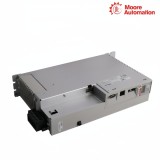
Copy| Product Name | Allen-Bradley 2198-S086-ERS4 / 2198-S130-ERS4 Kinetix 5700 single-axis inverter with ERS4 safety |
| Item NO. | 2913258 |
| Weight | 0.1 kg = 0.2205 lb = 3.5274 oz |
| Category | AB |
| Brand | ALLEN-BRADLEY |
| Creation Time | 2026-10-08 |
KINETIX 5700 · SINGLE-AXIS INVERTERS
Allen-Bradley 2198-S086-ERS4 / 2198-S130-ERS4 are Kinetix 5700 single-axis inverter modules with the ERS4 safety option. Each module supplies one controlled motor axis as part of the coordinated Kinetix 5700 common-bus drive system.
Allen-Bradley 2198-S086-ERS4 / 2198-S130-ERS4 form two inverter positions in a Kinetix 5700 common-bus system. The selected catalog number remains linked to its axis and safety configuration so the converter section, inverter section and controller project describe the same physical machine channel.

| Technical Item | 2198-S086-ERS4 | 2198-S130-ERS4 |
|---|---|---|
| Brand | Allen-Bradley | |
| Product Type | Kinetix 5700 single-axis inverter, ERS4 | |
| Brand Country | United States | |
| Safety Functions | STO, SS1 and safe monitoring | |
| DC Bus Input | 276...747 V DC | |
| Control Power | 24 V DC, 4.6 A | |
| PWM Frequency | 4 kHz | |
| Velocity-Loop Bandwidth | 400 Hz maximum | |
| Current-Loop Bandwidth | 1000 Hz | |
| Continuous Output Power @ 480 V | 29.7 kW | 44.9 kW |
| Continuous Output Current | 43 A rms | 65 A rms |
| Peak Output Current | 86 A rms | 130 A rms |
| Internal Capacitance | 560 µF | 840 µF |
| Power Dissipation @ 100% Rating | 475 W | 725 W |
| Approximate Weight | 5.21 kg (11.5 lb) | 5.44 kg (12.0 lb) |
| Drawing Dimension A | 85 mm (3.35 in.) | |
| Drawing Dimension B | 375 mm (14.8 in.) | |
| Drawing Dimension C | 433 mm (17.0 in.) | |
| Drawing Dimension D | 252 mm (9.92 in.) | |
| 24 V Control Inrush Current | 4.0 A | |
| Absolute/EnDat Feedback Cable | 90 m (295 ft) maximum | |
| Incremental Feedback Cable | 30 m (98.4 ft) maximum | |
The inverter position is commissioned only after the upstream bus source, local control circuit and motor branch have been identified.
Confirm that the intended Kinetix 5700 supply module feeds the inverter position through the common-bus assembly.
Associate the physical S086 or S130 position with the matching controller axis before motor cables are energized.
Trace the motor-power and feedback branches to the same machine axis and confirm network ownership before enable.
The safety functions are validated as a sequence of commanded states rather than inferred from the model suffix alone.
Command Safe Torque Off from the safety controller and confirm that the inverter removes torque-producing output.
Validate the Safe Stop sequence so the configured stop action completes before the torque-off state is reached.
Exercise the configured safe-monitoring condition and confirm that it reports through the safety-control path, not the motor circuit.
Use the actual continuous and peak current values when assigning the inverter to the bus. S086 is 43 A rms continuous and S130 is 65 A rms continuous, so the DC-bus and motor calculations must use the chosen model.
The ERS4 option provides Safe Torque Off, Safe Stop 1 and safe monitoring. Keep the ERS4 suffix in the controller and safety design so the selected safety-capable inverter is not reduced to a generic S086 or S130 module.
Both modules use 24 V DC control power at 4.6 A. Treat this as a separate control-power requirement from the 276...747 V DC bus that feeds the inverter stage.
S086 uses 560 µF and S130 with 840 µF internal capacitance, matching their different current classes. Use the selected catalog number when assessing the DC-bus assembly, not a single family value.
Their 100% rated-load dissipation is 475 W for S086 and 725 W for S130. Use the correct loss figure in the cabinet heat assessment even though both modules are 70 mm wide.
Both use a 4 kHz PWM frequency, 400 Hz maximum velocity-loop bandwidth and 1000 Hz current-loop bandwidth. These control characteristics are shared, while the current and power limits remain model-specific.
 www.mvme.cn
Moore Automation keeps manufacturer references, requested quantities and product condition visible from enquiry review through shipment confirmation.


Moore Automation Sales Team
Copyright © 2004–2026 www.mvme.cn. All rights reserved.
Disclaimer: Moore Automation Limited is an independent reseller and is not an authorized distributor or representative of the manufacturers featured on this website. Product names and trademarks belong to their respective owners.
No related record found